Subaru Legacy III (2000-2003 year). Service manual — part 260
ME(H6DO)-28
MECHANICAL
V-BELT
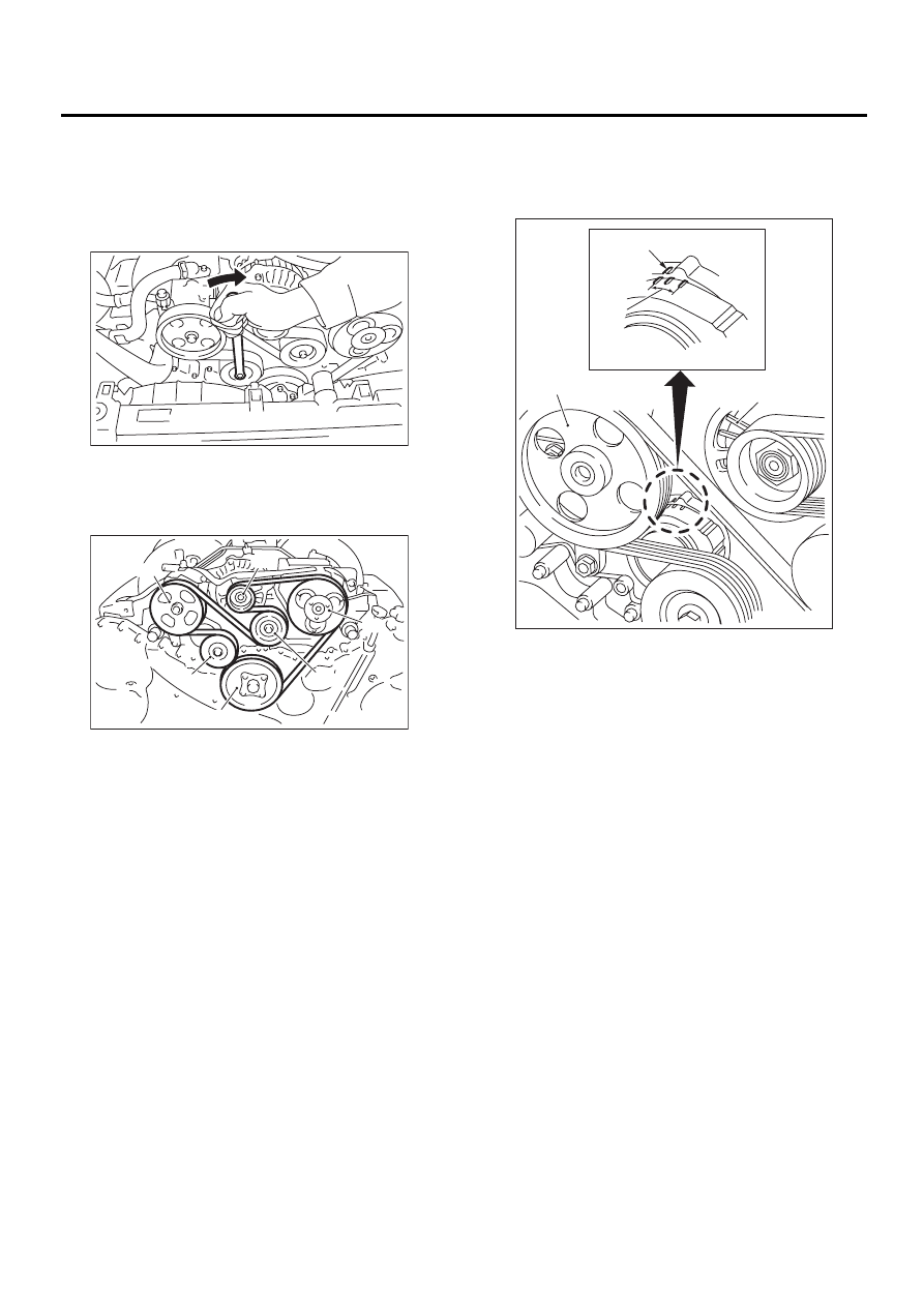
6. V-belt
A: REMOVAL
1) Fit the tool to the belt tensioner mounting bolt.
2) Turn the tool clockwise, and loosen the V-belt to
remove.
3) Remove the V-belt cover.
B: INSTALLATION
1) Install in the reverse order of removal.
C: INSPECTION
1) Replace belts, if cracks, fraying or wear is found.
2) Check that the V-belt automatic tensioner indica-
tor (A) is within the range (D).
(1) Power steering oil pump
(2) Belt tension adjuster
(3) Crankshaft pulley
(4) A/C compressor
(5) Belt idler
(6) Generator
ME-00473
ME-00474
( 1 )
( 6 )
( 4 )
( 5 )
( 2 )
( 3 )
(A) Indicator
(B) Generator
(C) Power steering oil pump
(D) Service limit
ME-00475
( B )
( A )
( D )
( C )
ME(H6DO)-29
MECHANICAL
ENGINE ASSEMBLY
7. Engine Assembly
A: REMOVAL
1) Set the vehicle on lift arms.
2) Open front hood fully and support with stay.
3) Raise rear seat, and turn floor mat up.
4) Release fuel pressure. <Ref. to FU(H6DO)-50,
RELEASING OF FUEL PRESSURE, OPERA-
TION, Fuel.>
5) Remove filler cap.
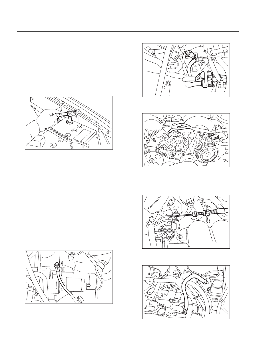
6) Disconnect battery ground cable.
7) Remove air intake duct, air cleaner case and air
intake chamber.
<Ref. to IN(H6DO)-7, REMOVAL, Air Intake
Duct.>, <Ref. to IN(H6DO)-6, REMOVAL, Air In-
take Chamber.> and <Ref. to IN(H6DO)-5, RE-
MOVAL, Air Cleaner.>
8) Lift up the vehicle.
9) Remove under cover.
10) Remove radiator from vehicle. <Ref. to
CO(H6DO)-27, REMOVAL, Radiator.>
11) Remove V-belt. <Ref. to ME(H6DO)-28, RE-
MOVAL, V-belt.>
12) Disconnect A/C pressure hoses from A/C com-
pressor. <Ref. to AC-42, REMOVAL, Flexible
Hose.>
13) Disconnect the following connectors and ca-
bles.
(1) Engine ground terminal
(2) Engine harness connectors
(3) Generator connector, terminal and A/C
compressor connector
(4) Accelerator cable
14) Disconnect the following hoses.
(1) Brake booster vacuum hose
IN-00068
ME-00476
(A) Generator connector and terminal
(B) A/C compressor connector
ME-00477
ME-00478
( A )
( B )
ME-00479
ME-00480
ME(H6DO)-30
MECHANICAL
ENGINE ASSEMBLY
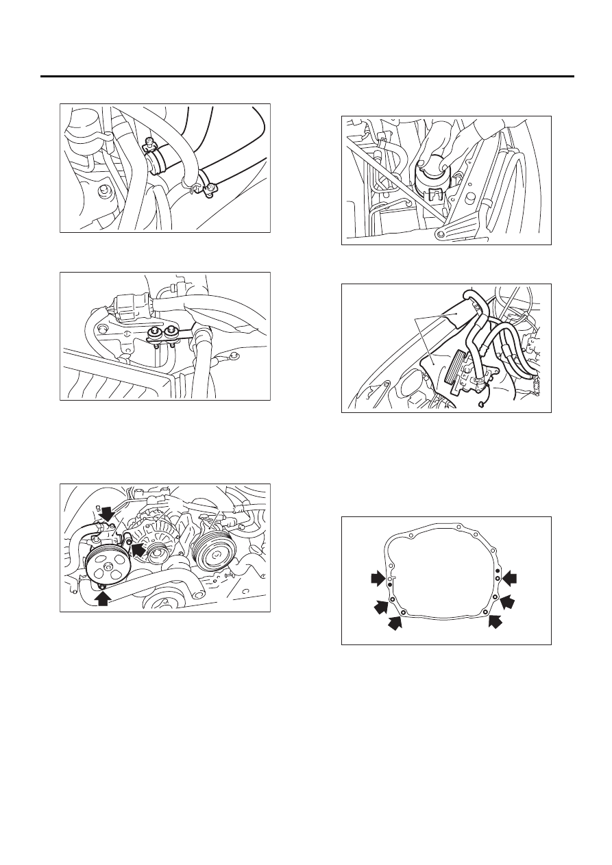
(2) Heater inlet outlet hose
15) Remove power steering pump from bracket.
(1) Remove pipe with bracket.
(2) Remove bolts which install power steering
pump bracket.
NOTE:
Do not separate the hose and the pipe from the
pump body.
(3) Remove power steering tank from the
bracket by pulling it upward.
(4) Place power steering pump on the right side
wheel apron.
16) Remove front exhaust pipe.
<Ref. to EX(H6DO)-5, REMOVAL, Front Exhaust
Pipe.>
17) Remove nuts which hold lower side of trans-
mission to engine.
(A) Power steering pump
(B) Generator
(C) A/C compressor
ME-00481
ME-00449
ME-00482
( A )
( B )
( C )
(A) Cloth
ME-00451
ME-00483
( A )
ME-00484
ME(H6DO)-31
MECHANICAL
ENGINE ASSEMBLY
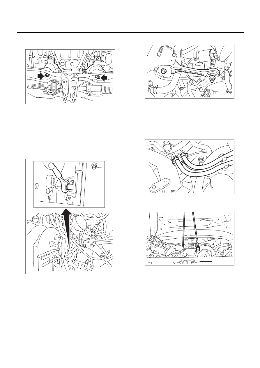
18) Remove nuts which install front cushion rubber
onto front crossmember.
19) Separate torque converter clutch from drive
plate.
(1) Lower the vehicle.
(2) Remove service hole plug (A).
(3) Remove bolts which hold torque converter
clutch to drive plate.
(4) Remove other bolts while rotating the en-
gine using ST.
ST
499977100
CRANK PULLEY WRENCH
20) Remove pitching stopper.
21) Disconnect fuel delivery hose, return hose and
evaporation hose.
CAUTION:
• Disconnect hose with its end wrapped with
cloth to prevent fuel from splashing.
• Catch fuel from hose into container.
22) Support engine with a lifting device and wire
ropes.
ME-00485
ME-00486
( A )
ME-00487
ME-00488
ME-00489
Нет комментариевНе стесняйтесь поделиться с нами вашим ценным мнением.
Текст