Subaru Legacy III (2000-2003 year). Service manual — part 258
ME(H6DO)-20
MECHANICAL
IDLE SPEED
3. Idle Speed
A: INSPECTION
1) Before checking idle speed, check the following:
(1) Ensure that air cleaner element is free from
clogging, ignition timing is correct, spark plugs
are in good condition, and that hoses are con-
nected properly.
(2) Ensure that malfunction indicator light
(CHECK ENGINE light) does not illuminate.
2) Warm-up the engine.
3) Stop the engine, and turn ignition switch to OFF.
4) When using SUBARU SELECT MONITOR
<Ref. to ME(H6DO)-14, SPECIAL TOOLS, PREP-
ARATION TOOL, General Description.>
(1) Insert the cartridge to SUBARU SELECT
MONITOR.
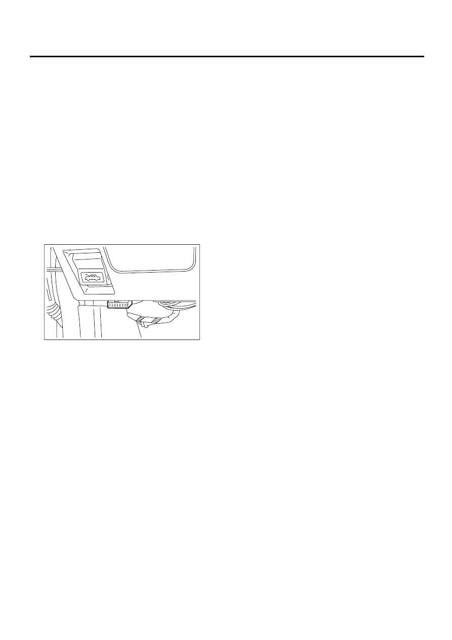
(2) Connect SUBARU SELECT MONITOR to
the data link connector.
(3) Turn ignition switch to ON, and SUBARU
SELECT MONITOR switch to ON.
(4) Select {2. Each System Check} in Main
Menu.
(5) Select {Engine Control System} in Selection
Menu.
(6) Select {1. Current Data Display & Save} in
Engine Control System Diagnosis.
(7) Select {1.12 Data Display} in Data Display
Menu.
(8) Start the engine, and read engine idle
speed.
NOTE:
• When using the OBD-II general scan tool, care-
fully read its operation manual.
• This ignition system provides simultaneous igni-
tion for #1 and #2 plugs. It must be noted that some
tachometers may register twice that of actual en-
gine speed.
5) Check idle speed when unloaded. (With head-
lights, heater fan, rear defroster, radiator fan, air
conditioning, etc. OFF)
Idle speed (No load and gears in N or P posi-
tion):
600
±±±±
50 rpm
6) Check idle speed when loaded. (Turn air condi-
tioning switch to “ON” and operate compressor for
at least one minute before measurement.)
Idle speed [A/C “ON”, no load and gears in N or
P position]:
700
±±±±
50 rpm
NOTE:
Idle speed cannot be adjusted manually because it
is controlled automatically. If idle speed is out of
specifications, refer to General On-board Diagno-
sis Table under “Engine Control System”. <Ref. to
EN(H6DO)-2, Basic Diagnostic Procedure.>
ME-00447

ME(H6DO)-21
MECHANICAL
IGNITION TIMING
4. Ignition Timing
A: INSPECTION
1) Before checking ignition timing, check the follow-
ing:
(1) Ensure that air cleaner element is free from
clogging, spark plugs are in good condition, and
that hoses are connected properly.
(2) Ensure that malfunction indicator light
(CHECK ENGINE light) does not illuminate.
2) Warm-up the engine.
3) Stop the engine, and turn ignition switch to OFF.
4) When using SUBARU SELECT MONITOR
<Ref. to ME(H6DO)-14, SPECIAL TOOLS, PREP-
ARATION TOOL, General Description.>
(1) Insert the cartridge to SUBARU SELECT
MONITOR.
(2) Connect SUBARU SELECT MONITOR to
the data link connector.
(3) Turn ignition switch to ON, and SUBARU
SELECT MONITOR switch to ON.
(4) Select {2. Each System Check} in Main
Menu.
(5) Select {Engine Control System} in Selection
Menu.
(6) Select {1. Current Data Display & Save} in
Engine Control System Diagnosis.
(7) Select {1.12 Data Display} in Data Display
Menu.
(8) Start engine at idle speed and check the ig-
nition timing.
Ignition timing [BTDC/rpm]:
10
°±
°±
°±
°±
8
°°°°
/600
If the timing is not correct, check the ignition
control system.
Refer to EN(H6DO) Engine Control System.
<Ref. to EN(H6DO)-2, Basic Diagnostic Proce-
dure.>
ME-00447
ME(H6DO)-22
MECHANICAL
VALVE CLEARANCE
5. Valve Clearance
A: INSPECTION
NOTE:
Inspection and adjustment of valve clearance
should be performed while engine is cold.
1) Set the vehicle on the lift.
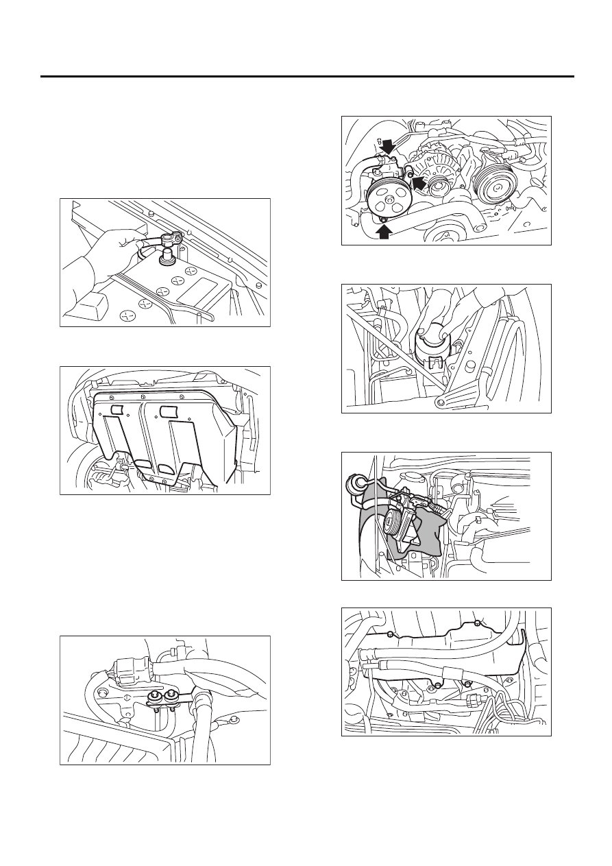
2) Disconnect battery ground cable.
3) Lift up the vehicle.
4) Remove under cover.
5) Lower the vehicle.
6) Place suitable container under the vehicle.
7) When inspecting RH side cylinder.
(1) Remove air intake duct and air cleaner
case. <Ref. to IN(H6DO)-7, REMOVAL, Air In-
take Duct.> and <Ref. to IN(H6DO)-5, REMOV-
AL, Air Cleaner.>
(2) Remove V-belt. <Ref. to ME(H6DO)-28,
REMOVAL, V-belt.>
(3) Remove power steering hose from bracket.
(4) Remove bolts which install power steering
pump bracket.
(5) Remove power steering tank from the
bracket by pulling it upward.
(6) Place power steering pump on the right side
wheel apron.
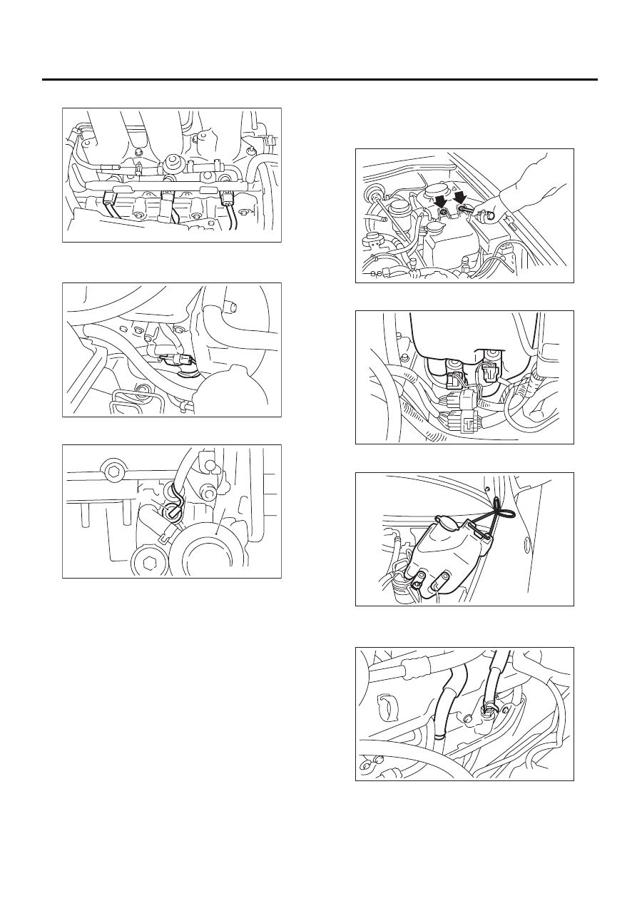
(7) Remove fuel pipe protector RH.
FU-00009
LU-00095
ME-00449
ME-00450
FU-00429
FU-00430
ME-00453
ME(H6DO)-23
MECHANICAL
VALVE CLEARANCE
(8) Disconnect fuel injector connectors.
(9) Disconnect front oxygen (A/F) sensor con-
nector.
(10)Disconnect oil pressure switch connector.
(11)Remove ignition coils. <Ref. to IG(H6DO)-7,
REMOVAL, Ignition Coil and Ignitor Assembly.>
(12)Remove rocker cover RH. <Ref. to
ME(H6DO)-50, REMOVAL, Camshaft.>
8) When inspecting LH side cylinder.
(1) Set the vehicle on the lift.
(2) Remove battery.
(3) Remove washer tank mounting bolts.
(4) Disconnect washer motor connectors.
(5) Move washer tank upward.
(6) Disconnect PCV and blow-by hose from
rocker cover LH.
(A) Oil pressure switch
(B) Oil filter
ME-00454
ME-00455
ME-00456
( B )
( A )
ME-00457
ME-00458
ME-00459
ME-00460
Нет комментариевНе стесняйтесь поделиться с нами вашим ценным мнением.
Текст