Subaru Legacy III (2000-2003 year). Service manual — part 846
PS-72
POWER ASSISTED SYSTEM (POWER STEERING)
PIPE ASSEMBLY
3.0 L and Turbo model
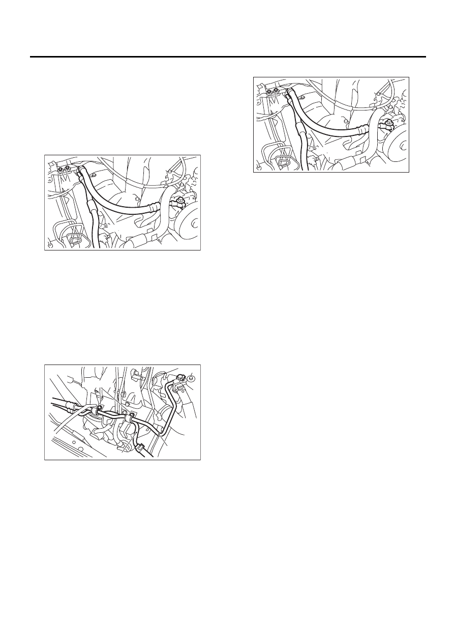
Disconnect pressure hose from oil pump. Discon-
nect return hose from reservoir tank.
CAUTION:
• Do not allow fluid from the hose end to come
into contact with pulley belt.
• To prevent foreign matter from entering the
hose and pipe, cover the open ends of them
with a clean cloth.
B: INSTALLATION
1) Tighten bolt A.
CAUTION:
Visually check that hose between tank and pipe
D is free from bending or twisting.
Except 3.0 L and Turbo model
3.0 L and Turbo model
(1) Connect pipe D or return hose to oil tank.
(2) Connect pipe C or pressure hose to oil
pump.
CAUTION:
Use anew gasket.
Tightening torque:
39 N·m (4.0 kgf-m, 28.9 ft-lb)
(3) Tighten bolt A.
Tightening torque:
13 N·m (1.3 kgf-m, 9.4 ft-lb)
(1) Bolt A
(2) Pressure hose
(3) Return hose
(1) Bolt A
(2) Pipe C
(3) Pipe D
PS-00222
( 1 )
( 2 )
( 3 )
( 1 )
( 2 )
( 3 )
PS-00221
(1) Bolt A
(2) Pressure hose
(3) Return hose
PS-00222
( 1 )
( 2 )
( 3 )
PS-73
POWER ASSISTED SYSTEM (POWER STEERING)
PIPE ASSEMBLY
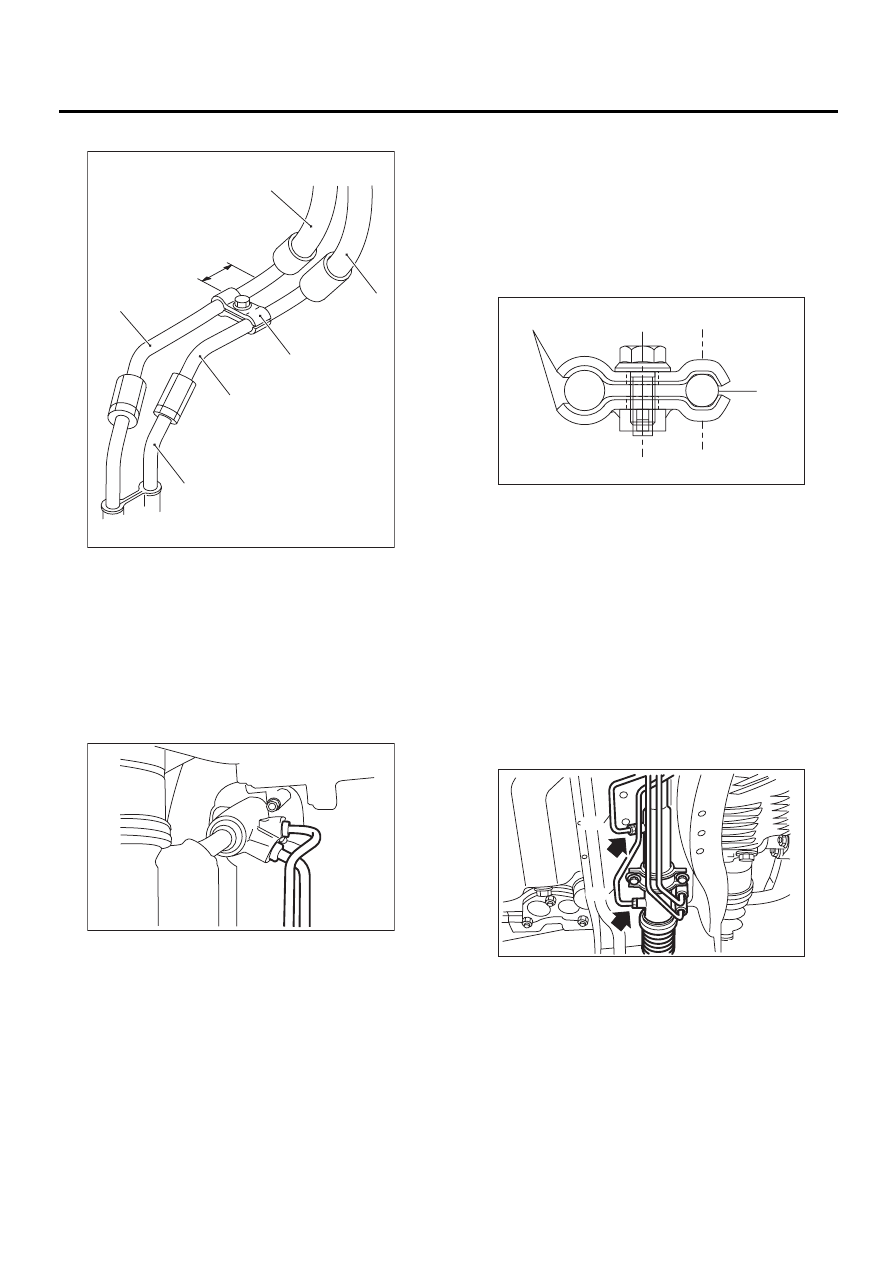
2) Temporarily connect pipes C and D.
RHD model
3) Temporarily install clamp E on pipes C and D,
and tighten clamp E firmly.
CAUTION:
Ensure that the letter “8” on each clamp are di-
agonally opposite each other as shown in fig-
ure.
Tightening torque:
7.4 N·m (0.75 kgf-m, 5.4 ft-lb)
4) Tighten joint nut.
Tightening torque:
15 N·m (1.5 kgf-m, 10.8 ft-lb)
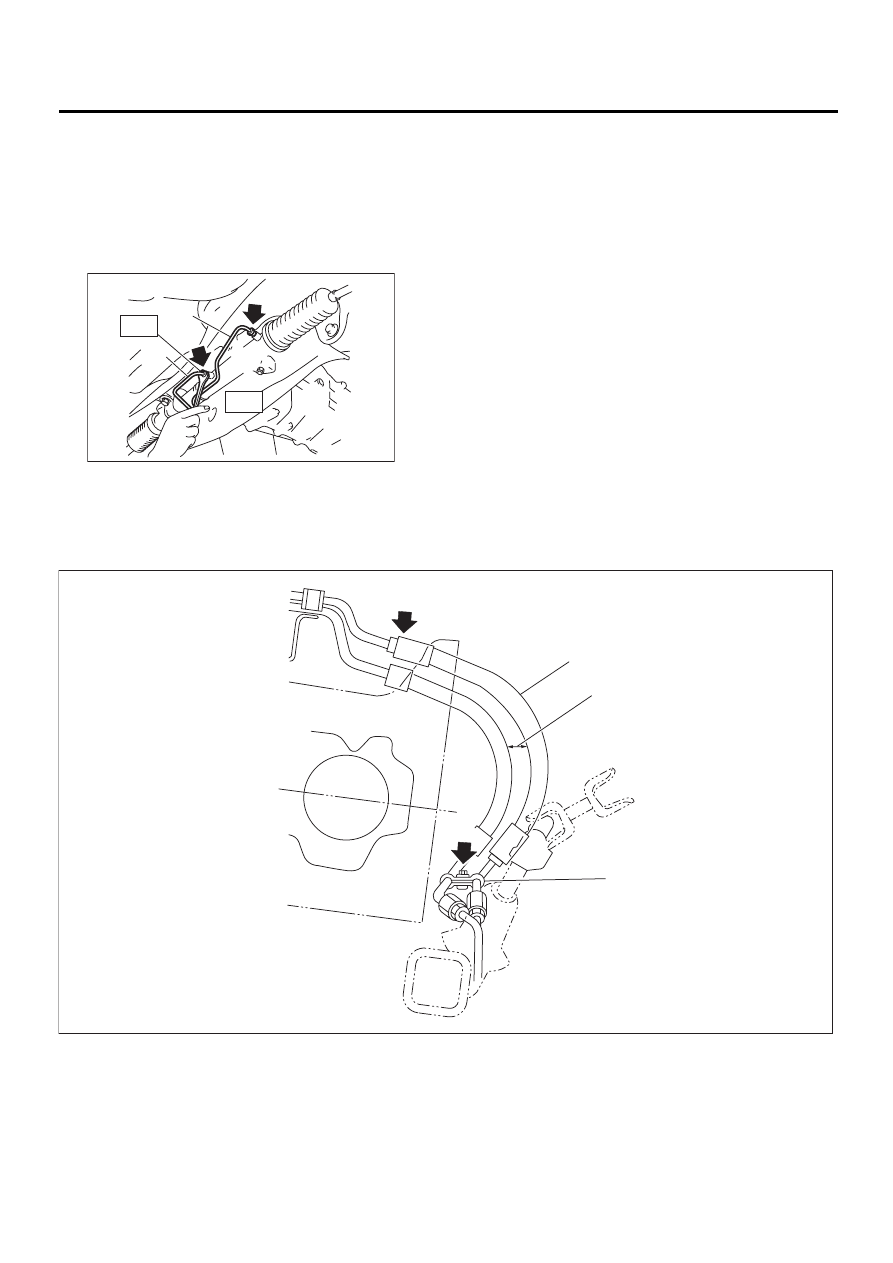
5) Connect pipe A and B.
Connect pipes A and B to four pipe joints of gear-
box. Connect upper pipe B first, and lower pipe A
second.
LHD model
Tightening torque:
13 N·m (1.3 kgf-m, 9.4 ft-lb)
(1) Return hose
(2) Pressure hose
(3) Approx. 30 mm (1.18 in)
(4) Clamp E
(5) Pipe C
(6) Pipe
(7) Pipe (on gearbox side)
PS-00178
( 1 )
( 2 )
( 3 )
( 4 )
( 5 )
( 6 )
( 7 )
PS-00288
(1) Clamp E
(2) Pipe C
(1) Pipe A
(2) Pipe B
PS-00223
letter
8
letter
8
( 1 )
( 2 )
PS-00026
( 1 )
( 2 )
PS-74
POWER ASSISTED SYSTEM (POWER STEERING)
PIPE ASSEMBLY
RHD model
Connect pipes A and B to four pipe joints of gear-
box. Connect upper pipe A first, and lower pipe B
second.
Tightening torque:
T1: 20 N·m (2.0 kgf-m, 14.5 ft-lb)
T2: 24 N·m (2.4 kgf-m, 17.4 ft-lb)
6) Install jack-up plate.
7) Connect battery ground cable.
8) Feed the specified fluid.
NOTE:
Never start the engine before feeding the fluid; oth-
erwise vane pump might be seized up.
LHD model
(1) Pipe A
(2) Pipe B
PS-00336
( 1 )
( 2 )
T1
T2
(1) High-pressure hose
(2) No interference is allowed
between hoses.
(3) Clearance between crossmember
and pipe: 3 - 8 (0.12 - 0.31)
PS-00179
( 1 )
( 2 )
( 3 )
( A )
( B )
PS-75
POWER ASSISTED SYSTEM (POWER STEERING)
PIPE ASSEMBLY
RHD model
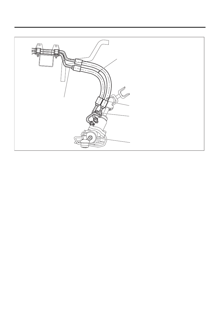
9) Finally check clearance between pipes and/or
hoses, as shown above.
If clearance between cruise control pump and pow-
er steering hose is less than 10 mm (0.39 in), pro-
ceed as follows:
(1) Move clamped section (A) (refer to figure
above.) down to a point where pipe is close to
crossmember.
Pipe-to-crossmember clearance:
10 mm (0.39 in), min.
(2) Check that clearance between cruise con-
trol pump and power steering hose is at least 10
mm (0.39 in). If it is not, bend section (B) down
until a clearance of at least 10 mm (0.39 in) is
obtained.
(1) No interference is allowed
between hoses.
(3) Clearance between side frame
and hose: 15 mm (0.59 in) or
more
(4) Clearance between crossmember
and pipe: 5 — 13 mm (0.20 —
0.51 in)
(2) Clearance between blow-by hose
and pipe: 3 — 5 mm (0.12 — 0.20
in)
(5) Steering gearbox
PS-00337
( 1 )
( 2 )
( 3 )
( 4 )
( 5 )
Нет комментариевНе стесняйтесь поделиться с нами вашим ценным мнением.
Текст