Subaru Legacy III (2000-2003 year). Service manual — part 844
PS-64
POWER ASSISTED SYSTEM (POWER STEERING)
STEERING GEARBOX [RHD MODEL]
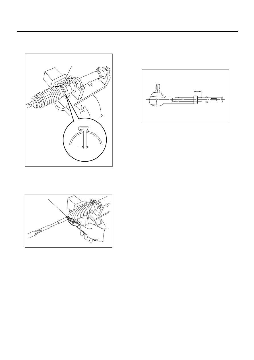
28) Install a new boot band. Using band clamp pli-
ers, caulk the boot band to make clearance of
caulking part 2 mm (0.079 in) or less.
29) Fix the boot end with clip (small).
30) After installing, check the boot end is posi-
tioned into groove on tie-rod.
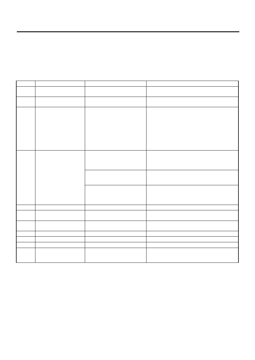
31) If the tie-rod end was removed, screw in the
lock nut and tie-rod end to screwed portion of tie-
rod, and then tighten the lock nut temporarily in a
position as shown in the figure.
Installed tie-rod length: L
15 mm (0.59 in)
(1) Boot band
(2) 2 mm (0.079 in) or less
(1) Clip
(2) 2 mm (0.079 in) or less
PS-00195
(1)
(2)
PS-00096
( 1 )
PS-00097
L
PS-65
POWER ASSISTED SYSTEM (POWER STEERING)
STEERING GEARBOX [RHD MODEL]
E: INSPECTION
1. BASIC INSPECTION
1) Clean all disassembled parts, and check for wear, damage, or any other faults, then repair or replace as
necessary.
2) When disassembling, check inside of gearbox for water. If any water is found, carefully check boot for
damage, input shaft dust seal, adjusting screw and boot clips for poor sealing. If faulty, replace with new
parts.
No.
Parts
Inspection
Corrective action
1
Input shaft
(1) Bend of input shaft
(2) Damage on serration
If bend or damage is excessive, replace entire gear-
box.
2
Dust seal
(1) Crack or damage
(2) Wear
If outer wall slips, lip is worn out or damage is found,
replace it with new one.
3
Rack and pinion
Poor mating of rack with pinion
(1) Adjust backlash properly.
By measuring turning torque of gearbox and sliding
resistance of rack, check if rack and pinion engage
uniformly and smoothly with each other.
(Refer to “Service limit”.)
(2) Keeping rack pulled out all the way so that all
teeth emerge, check teeth for damage.
Even if abnormality is found in either (1) or (2),
replace entire gearbox.
4
Gearbox unit
(1) Bend of rack shaft
(2) Bend of cylinder portion
(3) Crack or damage on cast iron
portion
Replace gearbox with new one.
(4) Wear or damage on rack bush
If free play of rack shaft in radial direction is out of
the specified range, replace gearbox with new one.
(Refer to “Service limit”.)
(5) Wear on input shaft bearing
If free plays of input shaft in radial and axial direc-
tions are out of the specified ranges, replace gear-
box with new one.
(Refer to “Service limit”.)
5
Boot
Crack, damage or deterioration
Replace.
6
Tie-rod
(1) Looseness of ball joint
(2) Bend of tie-rod
Replace.
7
Tie-rod end
Damage or deterioration on dust
seal
Replace.
8
Adjusting screw spring
Deterioration
Replace.
9
Boot clip
Deterioration
Replace.
10
Sleeve
Damage
Replace.
11
Pipes
(1) Damage to flared surface
(2) Damage to flare nut
(3) Damage to pipe
Replace.
PS-66
POWER ASSISTED SYSTEM (POWER STEERING)
STEERING GEARBOX [RHD MODEL]
2. SERVICE LIMIT
Make a measurement as follows. If it exceeds the
specified service limit, adjust or replace.
NOTE:
When making a measurement, vise gearbox by us-
ing ST. Never vise gearbox by inserting aluminum
plates, etc. between vise and gearbox.
ST
926200000
STAND
Sliding resistance of rack shaft:
Service limit
304 N (31 kgf, 68 lb) or less
Difference between left and right sliding resis-
tance
Less than 20%
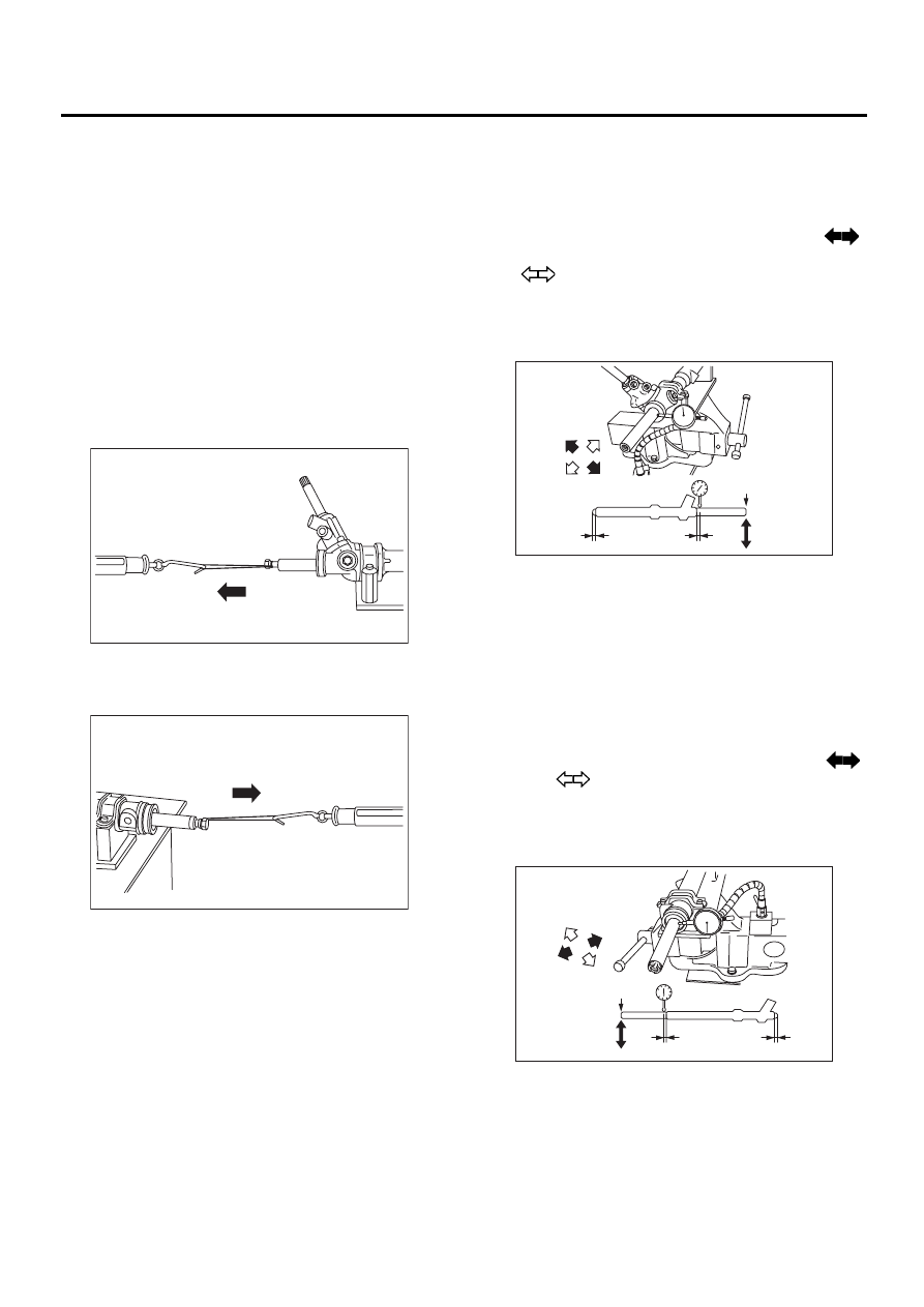
3. RACK SHAFT PLAY IN RADIAL DIREC-
TION
Right-turn steering:
Service limit
Less than 0.4 mm (0.016 in) (direction
)
Less than 0.6 mm (0.024 in) (direction
)
On condition
L: 5 mm (0.20 in)
P: 98 N (10 kgf, 22 lb)
Left-turn steering:
Service limit
Less than 0.4 mm (0.016 in) (direction
and )
On condition
L: 5 mm (0.20 in)
P: 98 N (10 kgf, 22 lb)
(1) Right turn steering
(1) Left turn steering
PS-00324
( 1 )
PS-00325
( 1 )
(1) Lower side
(2) Right turn
(3) Measuring point
(4) Right
(1) Lower side
(2) Left turn
(3) Measuring point
(4) Left
PS-00326
P
L
L
( 1 )
( 2 )
( 3 )
( 4 )
P
PS-00327
L
L
( 1 )
( 2 )
( 3 )
( 4 )
PS-67
POWER ASSISTED SYSTEM (POWER STEERING)
STEERING GEARBOX [RHD MODEL]
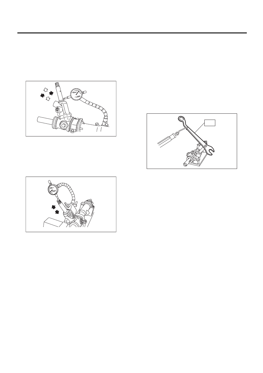
4. INPUT SHAFT PLAY
In radial direction:
Service limit
0.18 mm (0.0071 in) or less
On condition
P: 98 N (10 kgf, 22 lb)
In axial direction:
Service limit
0.27 mm (0.0106 in) or less
On condition
P: 20 — 49 N (2 — 5 kgf, 4 — 11 lb)
5. TURNING RESISTANCE OF GEARBOX
Using ST, measure gearbox turning resistance.
ST
926230000
SPANNER
Service limit:
Straight-ahead position within 30 mm (1.18
in) from rack center
Less than 11.18 N (1.14 kgf, 2.51 lb)
Maximum allowable resistance
15.79 N (1.61 kgf, 3.55 lb) or less
Difference between left and right sliding resis-
tance:
Less than 20%
PS-00328
P
PS-00329
P
PS-00330
ST
Нет комментариевНе стесняйтесь поделиться с нами вашим ценным мнением.
Текст