Subaru Legacy III (2000-2003 year). Service manual — part 641
CL-20
CLUTCH SYSTEM
FLYWHEEL
3. Flywheel
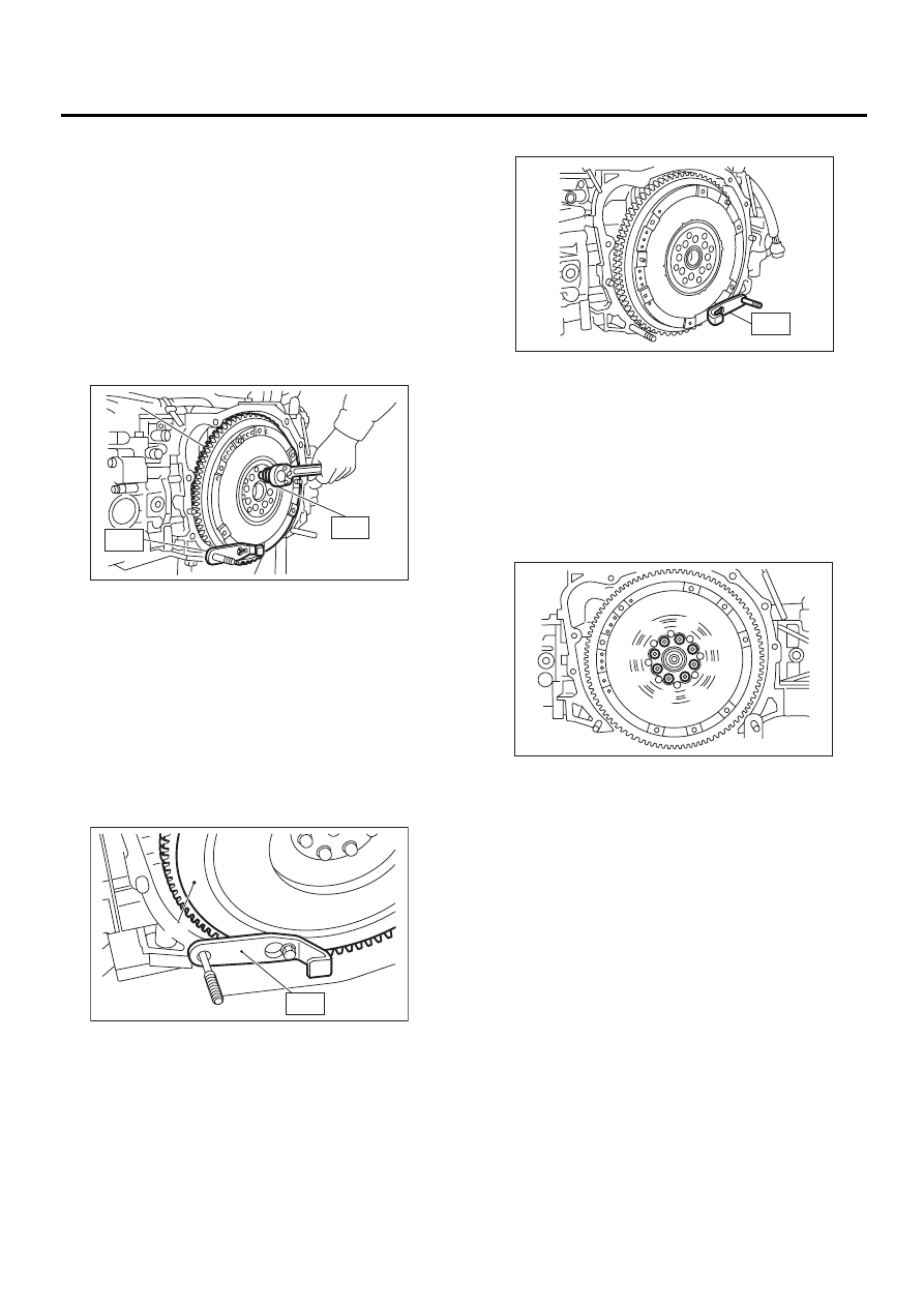
A: REMOVAL
1. EUROPE AND AUSTRALIA NON-TURBO
MODELS
1) Remove transmission assembly. <Ref. to MT-
32, REMOVAL, Manual Transmission Assembly.>
2) Remove clutch cover and clutch disc. <Ref. to
CL-15, REMOVAL, Clutch Disc and Cover.>
3) Remove flywheel using ST1 and ST2.
ST1
498497100
CRANKSHAFT STOPPER
ST2
499057000
TORX PLUS
2. EXCEPT EUROPE AND AUSTRALIA
NON-TURBO MODELS AND TURBO MOD-
EL
1) Remove transmission assembly. <Ref. to MT-
32, REMOVAL, Manual Transmission Assembly.>
2) Remove clutch cover and clutch disc. <Ref. to
CL-15, REMOVAL, Clutch Disc and Cover.>
3) Using ST, remove flywheel.
ST
498497100
CRANKSHAFT STOPPER
B: INSTALLATION
1. EUROPE AND AUSTRALIA NON-TURBO
MODELS
1) Install flywheel and ST.
ST
498497100
CRANKSHAFT STOPPER
2) Tighten the flywheel attaching bolts to the spec-
ified torque.
ST
499057000
TORX PLUS
NOTE:
Tighten flywheel installing bolts gradually. Each
bolt should be tightened to the specified torque in a
crisscross fashion.
Tightening torque:
72 N·m (7.3 kgf-m, 52.8 ft-lb)
3) Install clutch disc and cover. <Ref. to CL-15, EU-
ROPE AND AUSTRALIA NON-TURBO MODELS,
INSTALLATION, Clutch Disc and Cover.>
4) Install transmission assembly. <Ref. to MT-35,
INSTALLATION, Manual Transmission Assem-
bly.>
(A) Flywheel
(A) Flywheel
ST1
ST2
( A )
CL-00121
CL-00019
ST
( A )
ST
CL-00122
( 1 )
( 2 )
( 3 )
( 4 )
( 5 )
( 6 )
( 7 )
( 8 )
CL-00123
CL-21
CLUTCH SYSTEM
FLYWHEEL
2. EXCEPT EUROPE AND AUSTRALIA
NON-TURBO MODELS AND TURBO MOD-
EL
1) Install flywheel and ST.
ST
498497100
CRANKSHAFT STOPPER
2) Tighten the flywheel attaching bolts to the spec-
ified torque.
NOTE:
Tighten flywheel installing bolts gradually. Each
bolt should be tightened to the specified torque in
a crisscross fashion.
Tightening torque:
72 N·m (7.3 kgf-m, 52.8 ft-lb)
3) Install clutch disc and cover. <Ref. to CL-16, EX-
CEPT EUROPE AND AUSTRALIA NON-TURBO
MODELS AND TURBO MODEL, INSTALLATION,
Clutch Disc and Cover.>
4) Install transmission assembly. <Ref. to MT-35,
INSTALLATION, Manual Transmission Assem-
bly.>
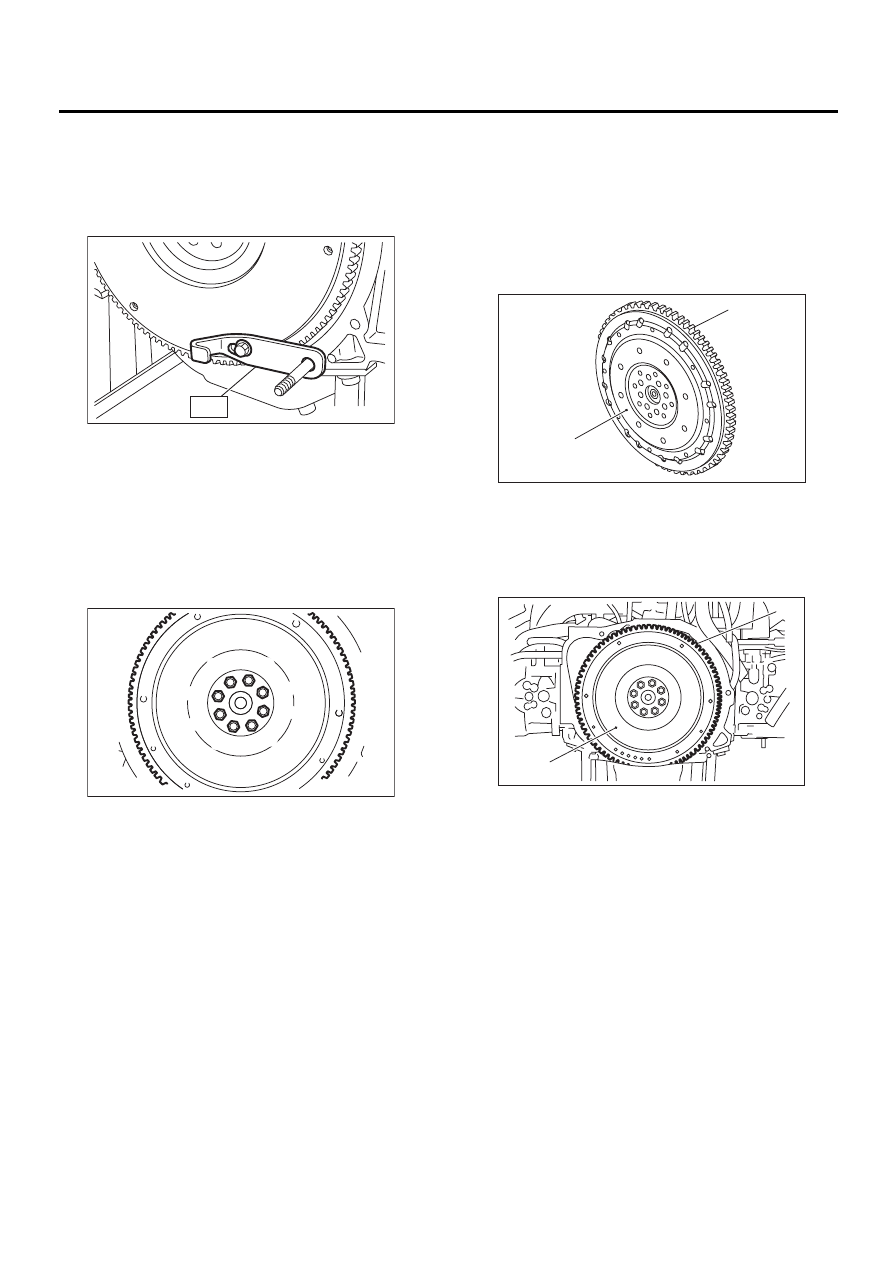
C: INSPECTION
CAUTION:
Since this bearing is grease sealed and is of a
non-lubrication type, do not wash with gaso-
line or any solvent.
1) Damage of facing and ring gear
If defective, replace flywheel.
Europe and Australia Non-Turbo models
Except Europe and Australia Non-Turbo
models and Turbo model
2) Smoothness of rotation
Rotate ball bearing applying pressure in thrust di-
rection.
3) If noise or excessive play is noted, replace fly-
wheel.
CL-00020
ST
( 1 )
( 2 )
( 3 )
( 4 )
( 5 )
( 6 )
( 7 )
( 8 )
CL-00021
(A) Flywheel
(B) Ring gear
(A) Flywheel
(B) Ring gear
( A )
( B )
CL-00124
CL-00022
( A )
( B )
CL-22
CLUTCH SYSTEM
RELEASE BEARING AND LEVER
4. Release Bearing and Lever
A: REMOVAL
1. NON-TURBO MODEL
1) Remove transmission assembly from vehicle
body.
<Ref. to MT-32, REMOVAL, Manual Transmission
Assembly.>
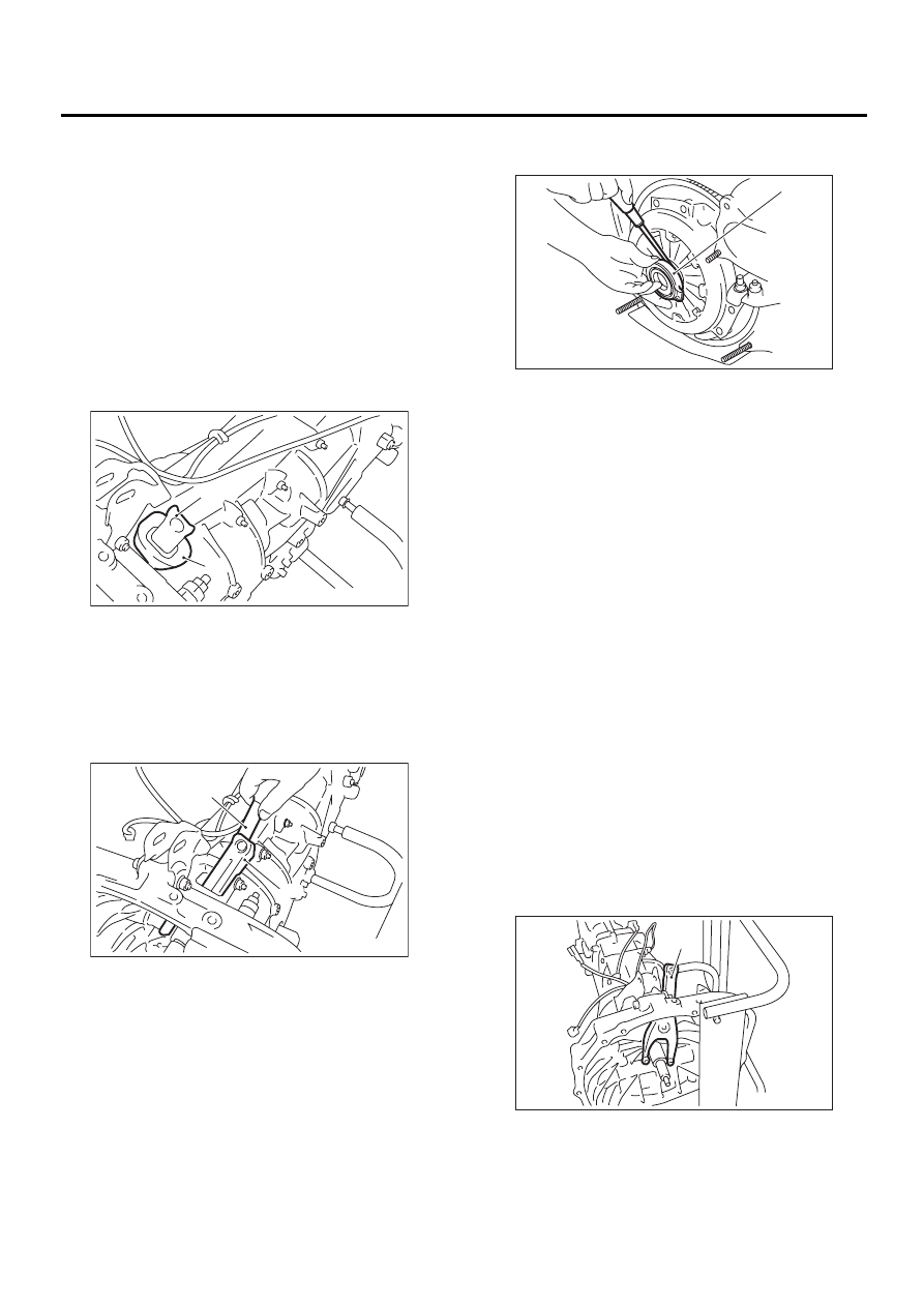
2) Remove the two clips from clutch release lever
and remove release bearing.
NOTE:
Be careful not to deform clips.
3) Remove release lever seal.
4) Remove release lever retainer spring from re-
lease lever pivot with a screwdriver by accessing it
through clutch housing release lever hole. Then re-
move release lever.
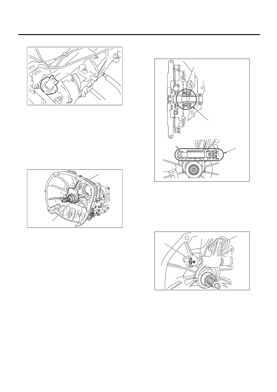
5) Remove pivot
2. TURBO MODEL
1) Remove the transmission assembly from vehicle
body. <Ref. to MT-32, REMOVAL, Manual Trans-
mission Assembly.>
2) Remove the clutch release lever from transmis-
sion.
3) Put the clutch release bearing in engine side.
4) Remove the clutch release bearing from clutch
cover using a flat-type screwdriver.
B: INSTALLATION
1. NON-TURBO MODEL
NOTE:
Before or during assembling, lubricate the following
points with a light coat of grease.
• Contact surface of lever and pivot
• Contact surface of lever and bearing
• Transmission main shaft spline (Use grease con-
taining molybdenum disulphide.)
• Contact surface of lever and operating cylinder
1) Install pivot.
Tightening torque:
15.7 N·m (1.6 kgf-m, 11.6 ft-lb)
2) While pushing release lever to pivot and twisting
it to both sides, fit retainer spring onto the constrict-
ed portion of pivot.
NOTE:
• Apply grease (SUNLIGHT 2: P/N 003602010) to
contact point of release lever and operating cylin-
der. <Ref. to CL-3, COMPONENT, General De-
scription.>
• Confirm that retainer spring is securely fitted by
observing it through the main case hole.
3) Install release bearing and fasten it with two
clips.
(A) Clutch release lever
(B) Release lever seal
(A) Clutch release lever
(B) Screwdriver
CL-00023
( A )
( B )
CL-00024
( A )
( B )
(A) Clutch release bearing
(A) Release lever
( A )
CL-00025
CL-00026
( A )
CL-23
CLUTCH SYSTEM
RELEASE BEARING AND LEVER
4) Install release lever seal.
5) Install transmission assembly.
<Ref. to MT-35, INSTALLATION, Manual Trans-
mission Assembly.>
2. TURBO MODEL
1) Install the release bearing on transmission.
2) Insert the release fork into release bearing tab.
3) Apply grease to the specified points:
• Spline FX2200 (Part No. 000040901)
• Shaft SUNLIGHT 2 (Part No. 003602010)
4) Insert the release fork shaft into release fork.
NOTE:
Make sure the cutout portion of release fork shaft
contacts spring pin.
(A) Release lever
(B) Release lever seal
(A) Release fork
(B) Release bearing
CL-00023
( A )
( B )
( A )
CL-00028
( B )
(A) Spline (FX2200)
(B) Shaft (SUNLIGHT 2)
(A) Release fork
(B) Release shaft
(C) Spring pin
CL-00029
( A )
( B )
CL-00030
( A )
( B )
( C )
Нет комментариевНе стесняйтесь поделиться с нами вашим ценным мнением.
Текст