Subaru Legacy III (2000-2003 year). Service manual — part 594
AT-110
AUTOMATIC TRANSMISSION (DIAGNOSTICS)
DIAGNOSTIC PROCEDURE WITH DIAGNOSTIC TROUBLE CODE (DTC)
15
CHECK HARNESS CONNECTOR BETWEEN
TRANSFER DUTY SOLENOID AND TRANS-
MISSION.
Measure resistance of harness between trans-
mission connector and transmission ground.
Connector & terminal
(T4) No. 6 — Transmission ground:
Does the measured value exceed the specified
value?
1 M
Ω
Even if “POWER”
indicator lights up,
the circuit has
returned to a nor-
mal condition at
this time. A tempo-
rary poor contact
of the connector or
harness may be
the cause. Repair
harness or con-
tact in the transfer
duty solenoid and
transmission con-
nector.
Repair short circuit
in harness
between transfer
duty solenoid and
transmission con-
nector.
Step
Value
Yes
No
AT-111
AUTOMATIC TRANSMISSION (DIAGNOSTICS)
DIAGNOSTIC PROCEDURE WITH DIAGNOSTIC TROUBLE CODE (DTC)
MEMO:
AT-112
AUTOMATIC TRANSMISSION (DIAGNOSTICS)
DIAGNOSTIC PROCEDURE WITH DIAGNOSTIC TROUBLE CODE (DTC)
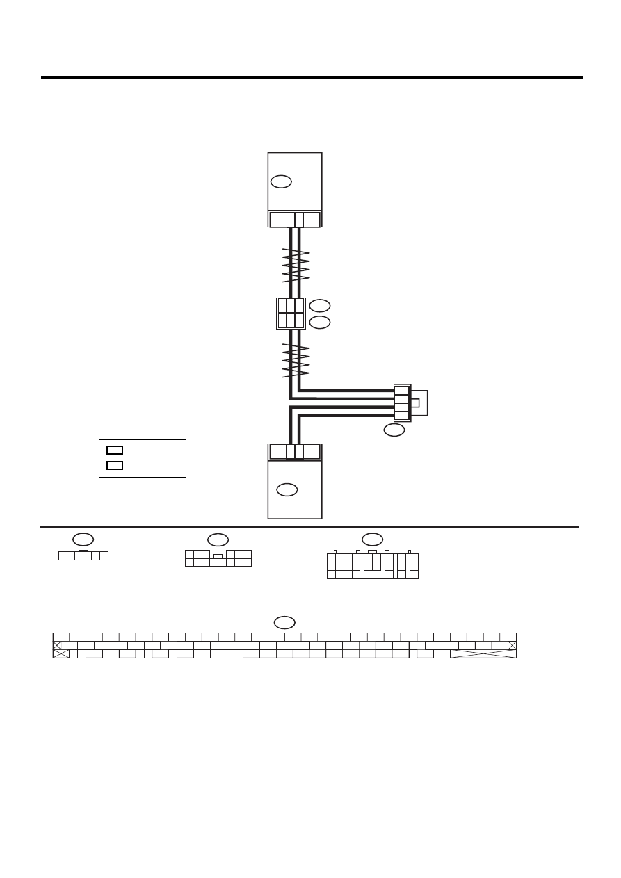
R: DTC 86 VDC COMMUNICATION SIGNAL
DIAGNOSIS:
Input signal circuit of TCM is open or shorted.
WIRING DIAGRAM:
AT-00784
TWISTED WIRE
TWISTED WIRE
B62
F45
B234
1 2 3 4 5 6
B56
1 2
7
8
9
5 6
3 4
10 11 12
19 20 21
13
14 15
16
17
18
22
23
24
9
18
1
4
6
3
B234
TCM
B56
83
81
VDC CM
F87
F87
56 57
59 60
62 63
65
82 83
80
27
28
25
26
23
24
21
22
19
20
17
18
15
16
13
14
11
12
9
10
7
8
5
6
3
4
1
2
54
55
52
53
50
51
81
48
49
46
47
44
45
78
79
76
77
75
42
43
40
41
74
72
73
70
71
39
37
38
35
36
69
67
68
66
33
34
61
64
31
32
29
30
58
51
LH
6
RH
2
JOINT
CONNECTOR
F96
LH
RH
: LHD MODEL
: RHD MODEL
1 2 3
4 5 6
7 8 9 10 11 12 13 14
AT-113
AUTOMATIC TRANSMISSION (DIAGNOSTICS)
DIAGNOSTIC PROCEDURE WITH DIAGNOSTIC TROUBLE CODE (DTC)
Step
Value
Yes
No
1
CHECK TROUBLE CODE.
Do multiple trouble codes appear in the on-
board diagnostics test mode?
DTC is displayed.
Go to another trou-
ble code.
2
CHECK HARNESS CONNECTOR BETWEEN
TCM AND VDCCM.
1) Turn ignition switch to OFF.
2) Disconnect connector from TCM and
VDCCM.
3) Measure resistance of harness between
TCM and VDCCM connector.
Connector & terminal
(B56) No. 18 — (F87) No. 81:
Is the measured value less than the speci-
fied value?
1
Ω
Repair open circuit
in harness
between TCM and
VDCCM, and poor
contact in cou-
pling connector.
3
CHECK HARNESS CONNECTOR BETWEEN
TCM AND VDCCM.
Measure resistance of harness between TCM
and VDCCM connector.
Connector & terminal
(B56) No. 9 — (F87) No. 83:
Is the measured value less than the specified
value?
1
Ω
Repair open circuit
in harness
between TCM and
VDCCM, and poor
contact in cou-
pling connector.
4
CHECK HARNESS CONNECTOR BETWEEN
TCM AND VDCCM.
Measure resistance of harness between TCM
and VDCCM connector.
Connector & terminal
(B56) No. 18 — Chassis ground:
Is the measured value less than the specified
value?
1 M
Ω
Repair short circuit
in harness
between TCM and
VDCCM connec-
tor.
5
CHECK HARNESS CONNECTOR BETWEEN
TCM AND VDCCM.
Measure resistance of harness between TCM
and VDCCM connector.
Connector & terminal
(B56) No. 9 — Chassis ground:
Is the measured value less than the specified
value?
1 M
Ω
Repair short circuit
in harness
between TCM and
VDCCM connec-
tor.
6
PREPARE OSCILLOSCOPE.
Do you have oscilloscope?
Oscilloscope is available.
7
CHECK INPUT SIGNAL FOR TCM.
1) Connect connectors to TCM and VDCCM.
2) Turn ignition switch to ON (engine OFF).
3) Measure voltage between TCM connector
and chassis ground.
Connector & terminal
(B56) No. 9 (+) — Chassis ground (
−−−−
):
(B56) No. 18 (+) — Chassis ground (
−−−−
):
Does input voltage value change?
Input voltage varies.
Repair poor con-
tact in VDCCM.
Нет комментариевНе стесняйтесь поделиться с нами вашим ценным мнением.
Текст