Subaru Legacy III (2000-2003 year). Service manual — part 927
WW-6
WIPER AND WASHER SYSTEMS
GENERAL DESCRIPTION
C: CAUTION
• Reconnect connectors and hoses securely.
After reconnecting, confirm that each function oper-
ates normally.
• Be careful that wire harnesses of airbag system
pass near electrical parts and switches.
• Wire harnesses and connectors of all airbag sys-
tem are yellow color. Do not use a tester on these
circuits.
• Care must be taken when installing the piping
hose so that no bending, jamming, etc. are caused.
• If even a little oil or grease such as silicon oil gets
in the tank and washer passages, an oil film easily
forms on the glass, causing the wiper to chatter and
judder. Therefore, be careful not to let this happen.

WW-7
WIPER AND WASHER SYSTEMS
WIPER AND WASHER SYSTEM
2. Wiper and Washer System
A: SCHEMATIC
1. WIPER AND WASHER (FRONT) LHD MODEL
<Ref. to WI-324, LHD MODEL, SCHEMATIC, Wiper and Washer System (Front).>
2. WIPER AND WASHER (FRONT) RHD MODEL
<Ref. to WI-325, RHD MODEL, SCHEMATIC, Wiper and Washer System (Front).>
3. WIPER AND WASHER (REAR) LHD MODEL
<Ref. to WI-326, LHD MODEL, SCHEMATIC, Wiper and Washer System (Rear).>
4. WIPER AND WASHER (REAR) RHD MODEL
<Ref. to WI-327, RHD MODEL, SCHEMATIC, Wiper and Washer System (Rear).>
B: INSPECTION
Symptom
Repair order
Wiper and washers do not operate.
(1) Wiper fuse (F/B No. 14, 15)
(2) Combination switch
(3) Wiper motor
(4) Wire harness
Wipers do not operate in LO or HI.
(1) Combination switch
(2) Wiper motor
(3) Wire harness
Wipers do not operate in INT.
(1) Combination switch
(2) Wiper motor
(3) Wire harness
Washer motor does not operate.
(1) Washer switch
(2) Washer motor
(3) Wire harness
Wipers do not operate when washer switch is ON.
(1) Washer motor
(2) Wire harness
Washer fluid spray does not operate.
(1) Washer motor
(2) Washer hose and nozzle
WW-8
WIPER AND WASHER SYSTEMS
COMBINATION SWITCH (WIPER)
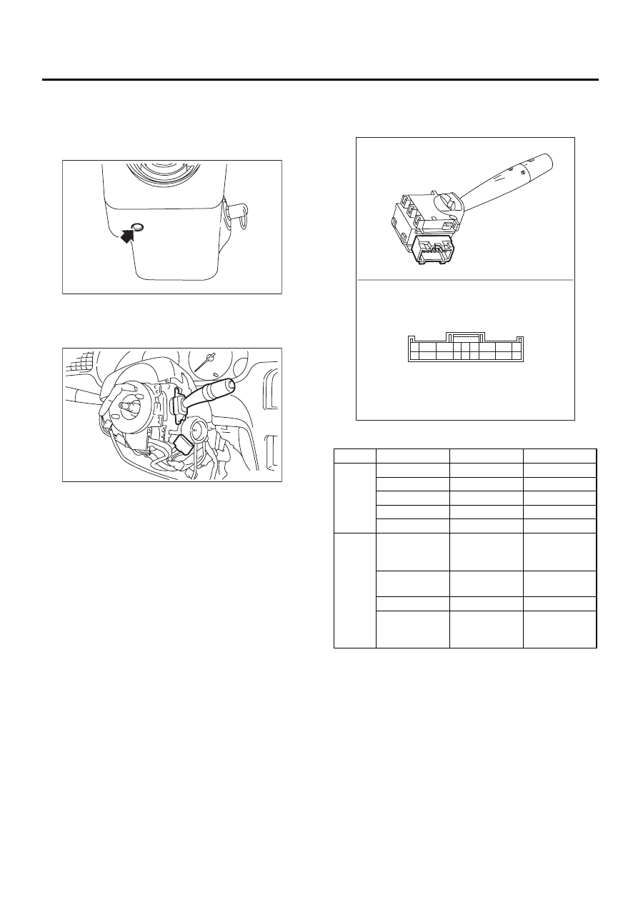
3. Combination Switch (Wiper)
A: REMOVAL
1) Loosen screw to remove a steering column cov-
er.
2) Disconnect connectors from combination
switches.
3) Loosen screw to remove combination switch.
B: INSTALLATION
Install in the reverse order of removal.
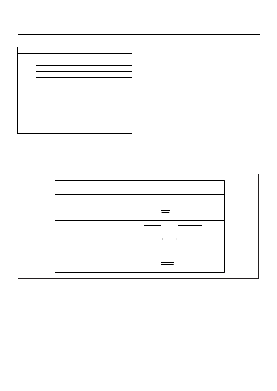
C: INSPECTION
• Inspect the continuity between each connector
terminal.
LHD model and RHD model with rear fog light:
If continuity is not as specified, replace the switch.
WW-00004
WW-00045
Switch position
Terminal No.
Standard
FRONT
OFF
7 and 16
Less than 1
Ω
INT
7 and 16
Less than 1
Ω
LO
7 and 17
Less than 1
Ω
HI
8 and 17
Less than 1
Ω
Washer ON
2 and 11
Less than 1
Ω
REAR
Washer ON
2 and 10
10 and 12
2 and 12
Less than 1
Ω
OFF
—
More than 1
M
Ω
ON
2 and 10
Less than 1
Ω
Washer ON
2 and 10
10 and 12
2 and 12
Less than 1
Ω
WW-00046
1
10
2
11
3
12
4
13
5
14
6
15
7
16
8
17
9
18
L O
L O
H I
H I
O F
F
O F
F
K i :
K i :
WW-9
WIPER AND WASHER SYSTEMS
COMBINATION SWITCH (WIPER)
RHD model without rear fog light:
If continuity is not as specified, replace the switch.
• Intermittent operation inspection
1) Turn the wiper switch to INT.
2) Adjust the intermittent control switch to MAX.
3) Apply battery voltage to switch terminals 16 and 2, and inspect the voltage of terminals 7 and 2. (Measure
the voltage from after the second time the wiper stops.)
If operation is not as specified, replace the switch.
Switch position
Terminal No.
Standard
FRONT
OFF
3 and 12
Less than 1
Ω
INT
3 and 12
Less than 1
Ω
LO
3 and 11
Less than 1
Ω
HI
2 and 11
Less than 1
Ω
Washer ON
8 and 17
Less than 1
Ω
REAR
Washer ON
8 and 16
16 and 18
8 and 18
Less than 1
Ω
OFF
—
More than 1
M
Ω
ON
8 and 18
Less than 1
Ω
Washer ON
8 and 16
16 and 18
8 and 18
Less than 1
Ω
(A) Switch position
(E) Non-variable
(I) 16 ± 6 sec.
(B) Voltage
(F) 12 V
(J) 3 ± 1 sec.
(C) MIN.
(G) 0 V
(D) MAX.
(H) Approx. 2 sec.
WW-00053
(A)
(B)
(C)
(H)
(I)
(J)
(D)
(F)
(G)
(F)
(G)
(F)
(G)
(E)
Нет комментариевНе стесняйтесь поделиться с нами вашим ценным мнением.
Текст