Subaru Legacy III (2000-2003 year). Service manual — part 419
ME(H4DOSTC)-40
MECHANICAL
ENGINE MOUNTING
10.Engine Mounting
A: REMOVAL
1) Remove the engine assembly. <Ref. to
ME(H4DOSTC)-31, REMOVAL, Engine Assem-
bly.>
2) Remove the engine mounting from engine as-
sembly.
B: INSTALLATION
Install in the reverse order of removal.
Tightening torque:
Engine mounting;
34 N·m (3.5 kgf-m, 25.3 ft-lb)
C: INSPECTION
Make sure there are no cracks or other damage.
ME(H4DOSTC)-41
MECHANICAL
PREPARATION FOR OVERHAUL
11.Preparation for Overhaul
A: PROCEDURE
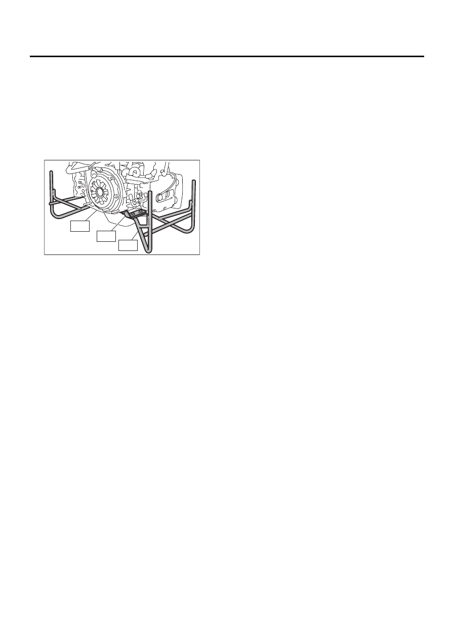
1) After removing the engine from body, secure it in
the ST shown below.
ST1
498457000
ENGINE STAND ADAPTER
RH
ST2
498457100
ENGINE STAND ADAPTER
LH
ST3
499817000
ENGINE STAND
2) In this section the procedures described under
each index are all connected and stated in order. It
will be the complete procedure for overhauling of
the engine itself when you go through all steps in
the process.
Therefore, in this section, to conduct the particular
procedure within the flow of a section, you need to
go back and conduct the procedure described pre-
viously in order to do that particular procedure.
ST2
ST3
ME-00057
ST1
ME(H4DOSTC)-42
MECHANICAL
V-BELT
12.V-belt
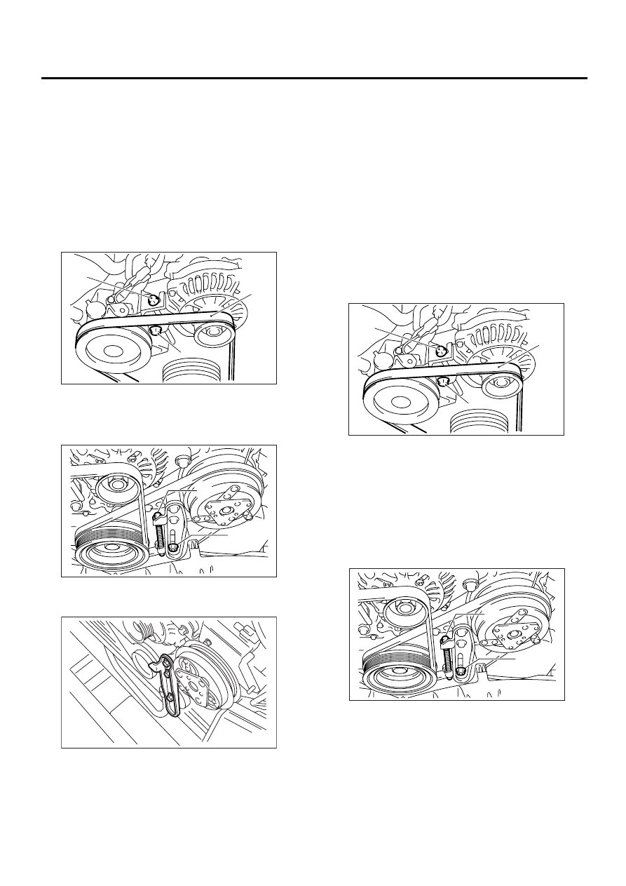
A: REMOVAL
1. FRONT SIDE BELT
NOTE:
Perform the following procedures 1) to 4) with the
engine installed to the body.
1) Remove the V-belt cover.
2) Loosen the lock bolt (A).
3) Loosen the slider bolt (B).
4) Remove the front side belt (C).
2. REAR SIDE BELT
1) Loosen the lock nut (A).
2) Loosen the slider bolt (B).
3) Remove the A/C belt.
4) Remove the A/C belt tensioner.
B: INSTALLATION
1. FRONT SIDE BELT
CAUTION:
Wipe off any oil or water on the belt and pulley.
1) Install the belt (C), and tighten the slider bolt so
as to obtain the specified belt tension. <Ref. to
ME(H4DOSTC)-43, INSPECTION, V-belt.>
2) Tighten the lock bolt (A).
3) Tighten the slider bolt (B).
Tightening torque:
Lock bolt through bolt:
25 N·m (2.5 kgf-m, 18.1 ft-lb)
Slider bolt:
8 N·m (0.8 kgf-m, 5.5 ft-lb)
2. REAR SIDE BELT
1) Install the belt, and tighten the slider bolt (B) so
as to obtain the specified belt tension. <Ref. to
ME(H4DOSTC)-43, INSPECTION, V-belt.>
2) Tighten the lock nut (A).
Tightening torque:
Lock nut (A);
22.6 N·m (2.3 kgf-m, 16.6 ft-lb)
(A)
(C)
(B)
ME-00059
(A)
(B)
ME-00060
ME-00061
(A)
(C)
(B)
ME-00059
(A)
(B)
ME-00060
ME(H4DOSTC)-43
MECHANICAL
V-BELT
C: INSPECTION
1) Replace the belts, if cracks, fraying or wear is
found.
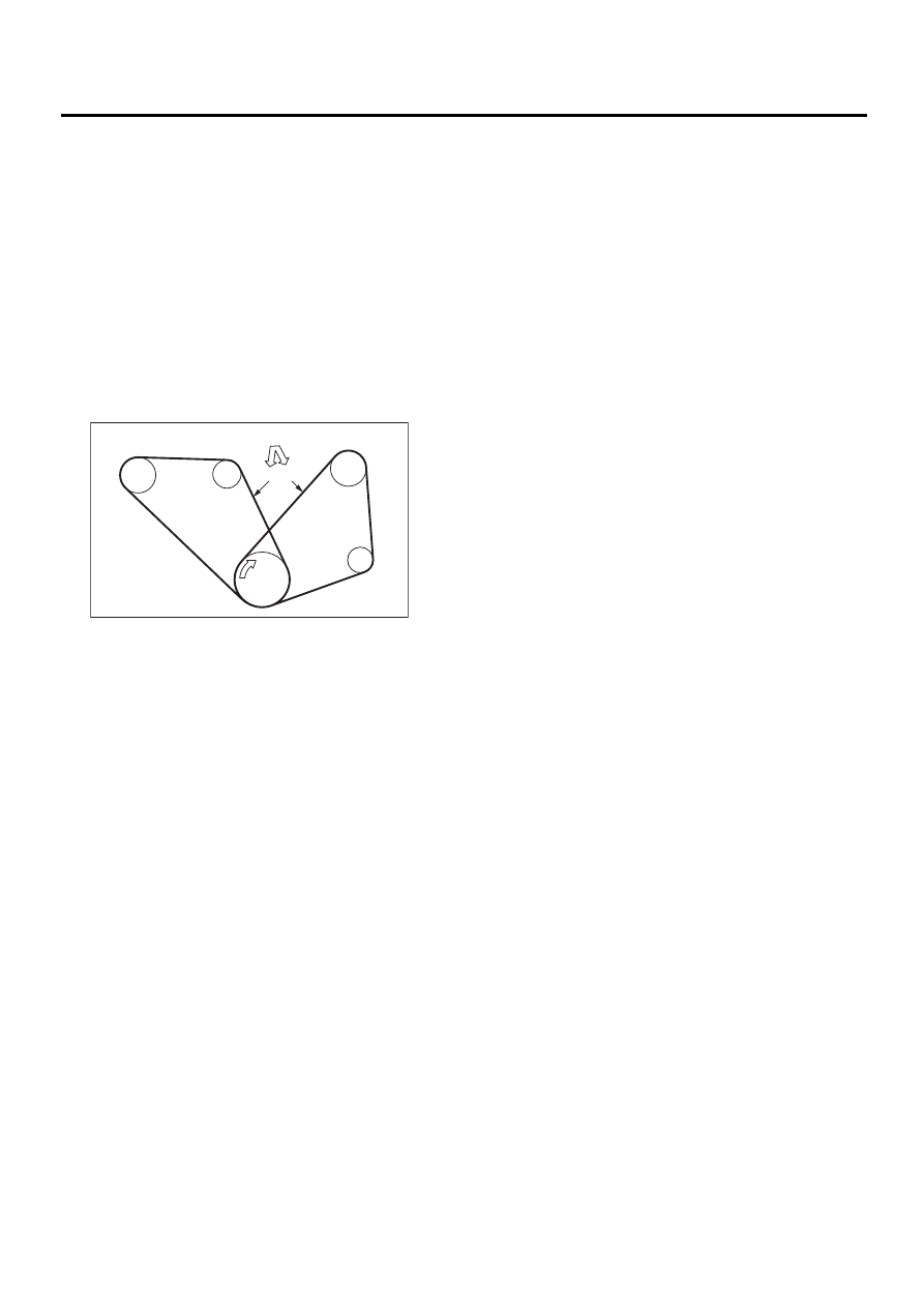
2) Check the drive belt tension and adjust it if nec-
essary by changing generator installing position
and/or idler pulley installing position.
Belt tension
(A)
replaced: 7 — 9 mm (0.276 — 0.354 in)
reused: 9 — 11 mm (0.354 — 0.433 in)
(B)*
replaced: 7.5 — 8.5 mm (0.295 — 0.335 in)
reused: 9.0 — 10.0 mm (0.354 — 0.394 in)
*: with air conditioner
C/P Crankshaft pulley
GEN Generator
P/S Power steering oil pump pulley
A/C Air conditioning compressor pulley
I/P Idler pulley
ME-00062
C/P
I/P
P/S
A/C
GEN
( A ) ( B )
98 N (10 kgf, 22lb)
Нет комментариевНе стесняйтесь поделиться с нами вашим ценным мнением.
Текст