Subaru Legacy III (2000-2003 year). Service manual — part 417
ME(H4DOSTC)-32
MECHANICAL
ENGINE ASSEMBLY
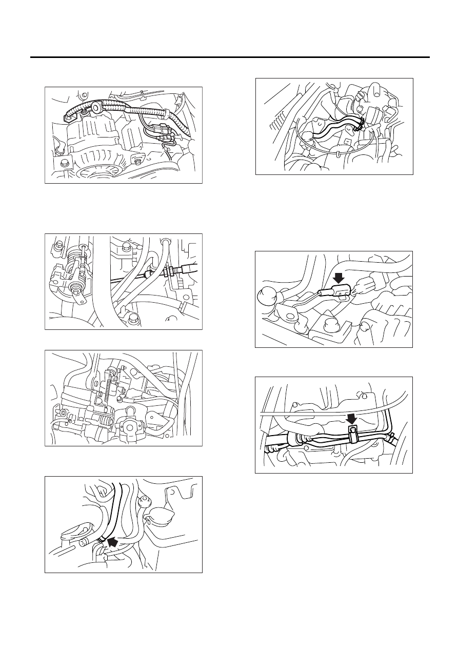
(4) Generator connector, terminal and A/C
compressor connectors
(5) Accelerator cable (MT vehicles)
(6) Clutch release spring (MT vehicles)
12) Disconnect the following hoses.
(1) Brake booster vacuum hose
(2) Heater inlet outlet hose
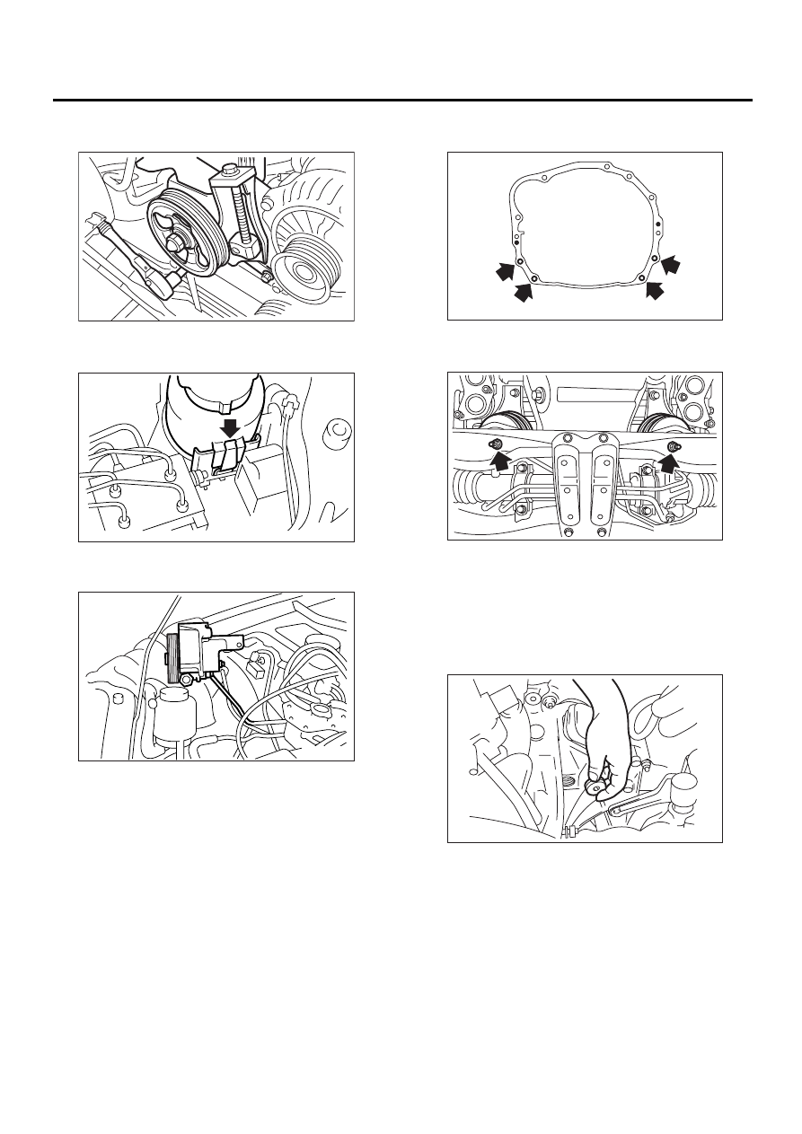
13) Remove the power steering pump from brack-
et.
(1) Loosen the lock bolt and slider bolt, and
then remove the front side V-belt. <Ref. to
ME(H4DOSTC)-42, REMOVAL, V-belt.>
(2) Disconnect the power steering switch con-
nector.
(3) Remove the pipe with bracket from intake
manifold.
(A) A/C compressor connector
(B) Generator connector and terminal
ME-00628
ME-00031
ME-00032
ME-00629
ME-00630
ME-00035
ME-00631
ME(H4DOSTC)-33
MECHANICAL
ENGINE ASSEMBLY
(4) Remove the power steering pump from en-
gine.
(5) Remove the power steering tank from
bracket by pulling it upward.
(6) Place the power steering pump on right side
wheel apron.
14) Lift-up the vehicle.
15) Remove the ATF cooler pipe from frame. (AT
vehicles)
16) Remove the center exhaust pipe. <Ref. to
EX(H4DOSTC)-7, REMOVAL, Center Exhaust
Pipe.>
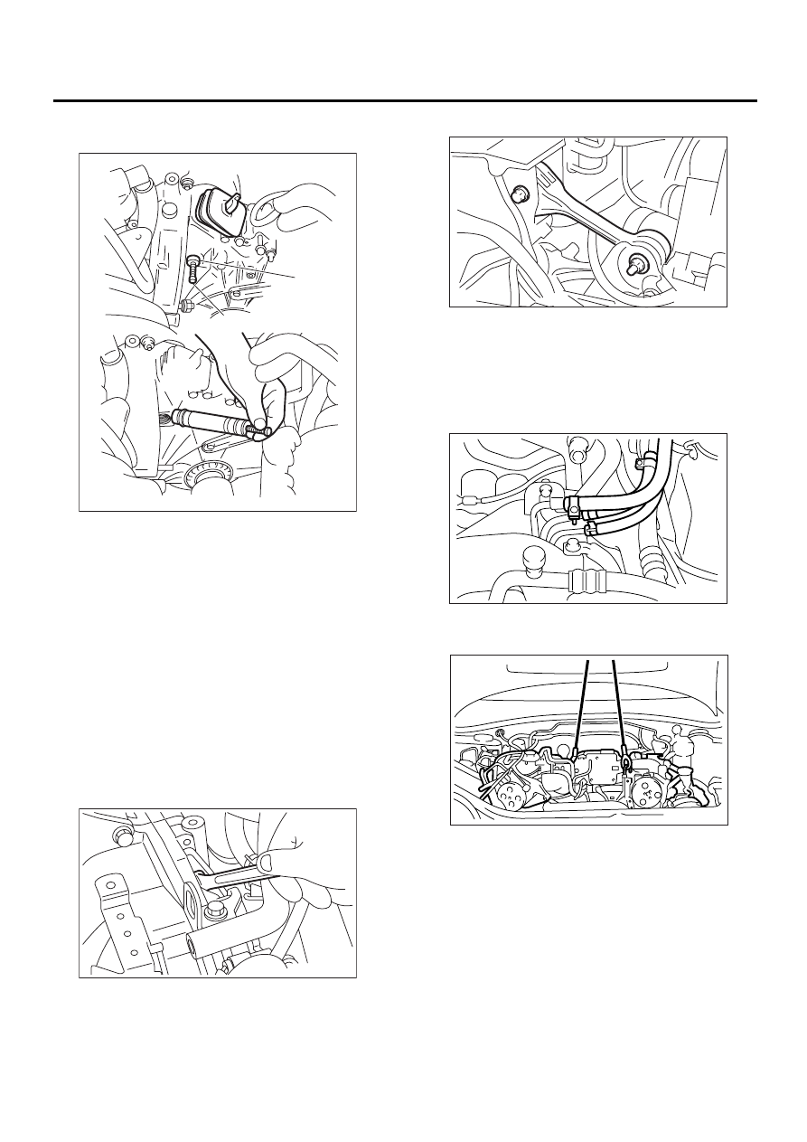
17) Remove the nuts which hold lower side of
transmission to engine.
18) Remove the nuts which install front cushion
rubber onto front crossmember.
19) Lower the vehicle.
20) Separate the clutch release fork from release
bearing. (MT vehicles)
(1) Remove the clutch operating cylinder from
transmission.
(2) Remove the plug using a 10 mm hexagon
wrench.
ME-00037
ME-00038
ME-00039
ME-00040
ME-00041
ME-00042
ME(H4DOSTC)-34
MECHANICAL
ENGINE ASSEMBLY
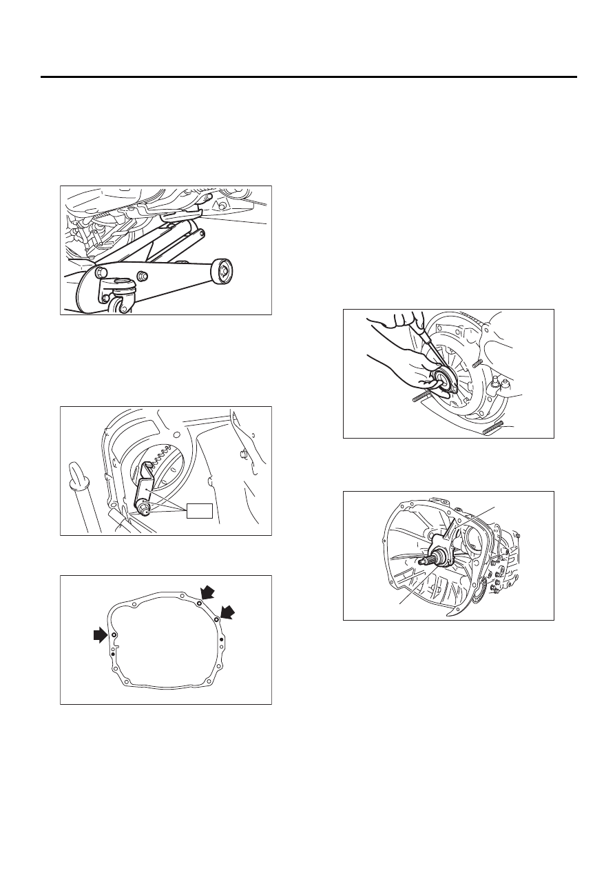
(3) Screw the 6 mm dia. bolt into release fork
shaft, and remove it.
(4) Raise the release fork, and then unfasten
the release bearing tabs to free release fork.
NOTE:
Step (4) is required to prevent interference with en-
gine when removing the engine from transmission.
21) Separate the torque converter clutch from drive
plate. (AT vehicles)
(1) Lower the vehicle.
(2) Remove the service hole plug.
(3) Remove the bolts which hold torque con-
verter clutch to drive plate.
(4) Remove the other bolts while rotating the
engine using socket wrench.
22) Remove the pitching stopper.
23) Disconnect the fuel delivery hose, return hose
and evaporation hose.
NOTE:
• Catch fuel from the hose into container.
• Disconnect the hose with its end wrapped with
cloth to prevent fuel from splashing.
24) Support the engine with a lifting device and
wire ropes.
(A) Shaft
(B) Bolt
( A )
( B )
ME-00043
ME-00044
MT-00069
ME-00045
ME-00047
ME(H4DOSTC)-35
MECHANICAL
ENGINE ASSEMBLY
25) Support the transmission with a garage jack.
NOTE:
Before moving the engine away from transmission,
check to be sure no work has been overlooked. Do-
ing this is very important in order to facilitate rein-
stallation and because transmission lowers under
its own weight.
26) Separation of the engine and transmission.
(1) Remove the starter. <Ref. to
SC(H4DOSTC)-6, REMOVAL, Starter.>
(2) Install the ST to torque converter clutch
case. (AT vehicles)
ST
498277200
STOPPER SET
(3) Remove the bolts which hold right upper
side of transmission to engine.
27) Remove the engine from vehicle.
(1) Slightly raise the engine.
(2) Raise the transmission with garage jack.
(3) Move the engine horizontally until the main-
shaft is withdrawn from clutch cover.
(4) Slowly move the engine away from engine
compartment.
NOTE:
Be careful not to damage adjacent parts or body
panels with crank pulley, oil pressure gauge, etc.
28) Remove the front cushion rubbers.
B: INSTALLATION
1) Install the clutch release fork and bearing onto
transmission. (MT vehicles)
(1) Remove the release bearing from clutch
cover with flat type screw driver.
(2) Install the release bearing on transmission.
(3) Install the release fork into release bearing
tab.
ME-00048
ME-00049
ST
ME-00050
(A) Release fork
(B) Release bearing
ME-00051
( A )
( B )
ME-00052
Нет комментариевНе стесняйтесь поделиться с нами вашим ценным мнением.
Текст