Subaru Legacy III (2000-2003 year). Service manual — part 542
AT-62
AUTOMATIC TRANSMISSION
CONTROL VALVE BODY
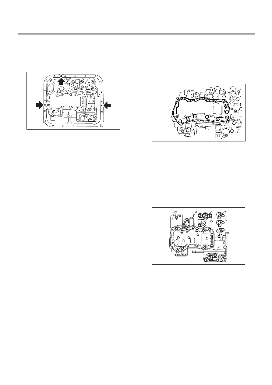
7) Apply liquid gasket fully to three holes other than
screw holes on transmission case.
Liquid gasket:
THREE BOND 1217B (Part No.
K0877YA020)
8) Install the oil pan.
Tightening torque:
5 N·m (0.5 kgf-m, 3.6 ft-lb)
9) Pour ATF into the oil charge pipe.
Recommended fluid:
Dexron III type automatic transmission flu-
id
Fluid capacity:
Fill the same amount of fluid drained from
drain plug hole.
10) Check the level of ATF.
<Ref. to AT-30, Automatic Transmission Fluid.>
C: DISASSEMBLY
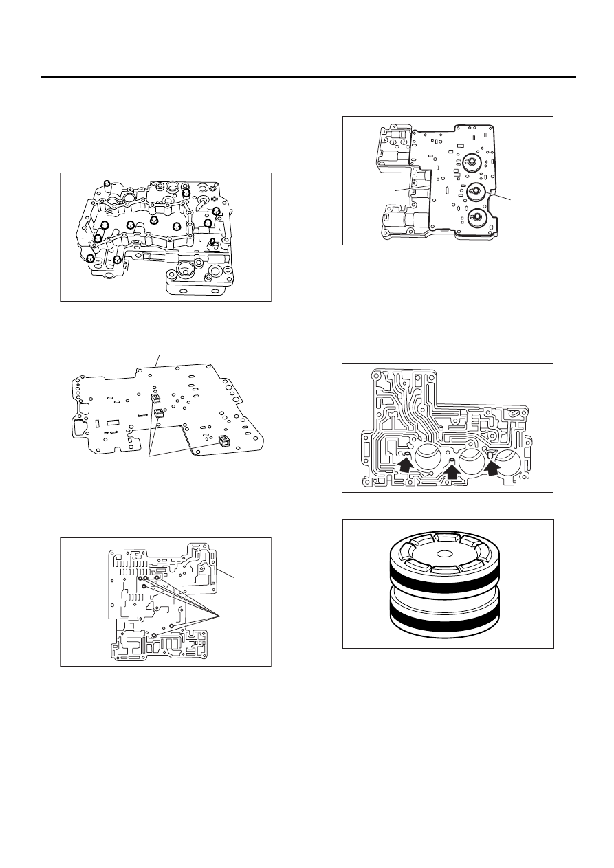
1) Remove oil strainer from lower control valve
body.
NOTE:
Arrange the removed bolts in good order to assem-
ble in the same place as disassembly, because the
bolts length are different.
2) Remove the duty solenoids, solenoids and sen-
sor from the lower valve body.
NOTE:
Arrange the removed bolts in good order to assem-
ble in the same place as disassembly, because the
bolts length are different.
AT-00052
(A) Short bolt
(B) Middle bolt
(C) Long bolt
(A) Lock-up duty solenoid (Blue)
(B) Low clutch timing solenoid (Gray)
(C) Line pressure duty solenoid (Red)
(D) Shift solenoid 1 (Yellow)
(E) Shift solenoid 2 (Green)
(F) 2-4 brake timing solenoid (Black)
(G) 2-4 brake duty solenoid (Red)
(H) Sport shift solenoid (Beige) (if equipped)
AT-00065
A
A
B
A
A
A
C
A
C
C
A
B
A
C
C
C
AT-00903
( A )
( B )
( C )
( D )
( E )
( F )
( G )
( H )
AT-63
AUTOMATIC TRANSMISSION
CONTROL VALVE BODY
3) Remove the upper-lower valve body tightening
bolts.
NOTE:
Arrange the removed bolts in good order to assem-
ble in the same place as disassembly, because the
bolts length are different.
4) Remove the lower valve body.
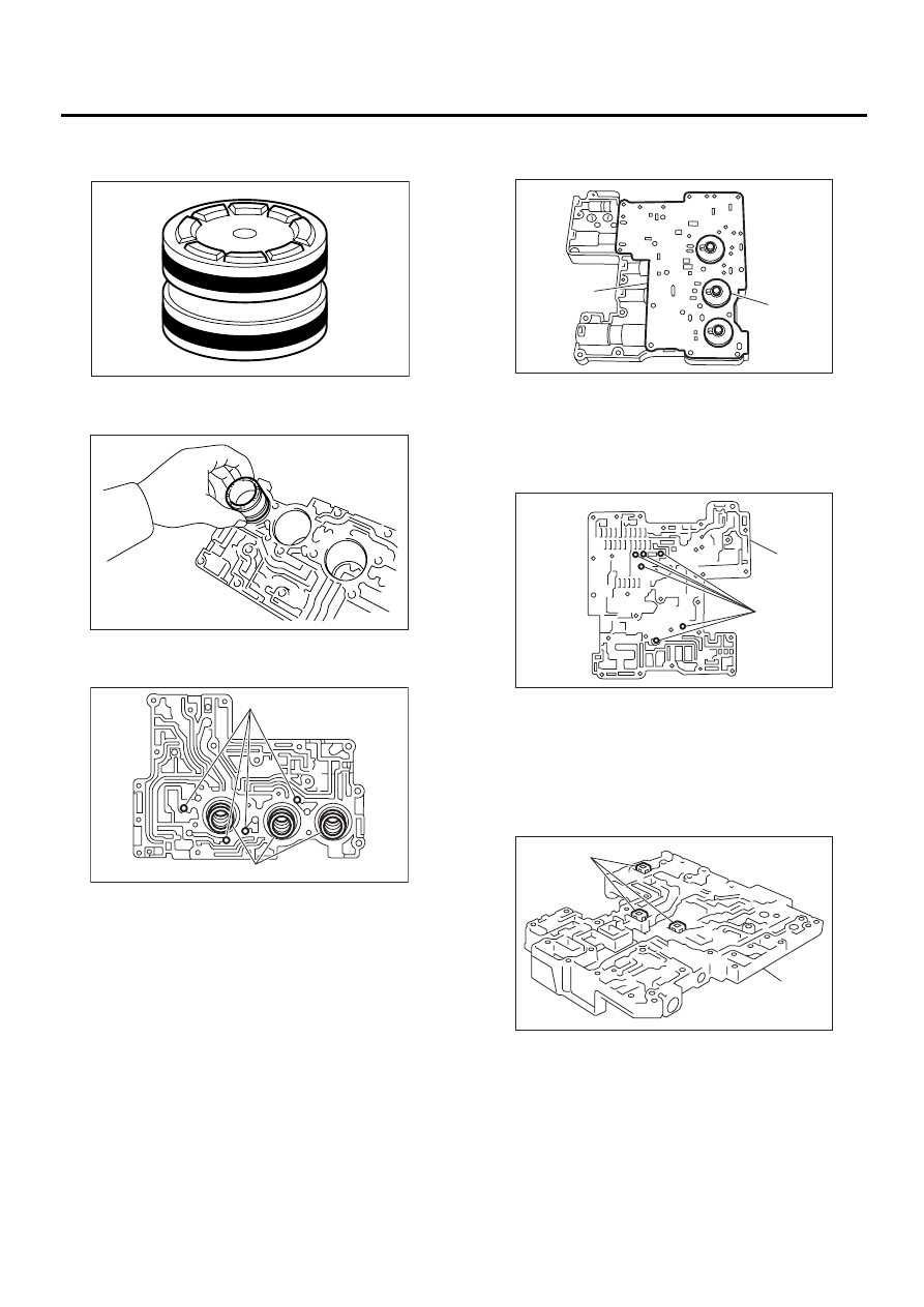
5) Remove the oil filter and plate.
6) Remove six steel balls from middle valve body.
7) Remove the middle valve body.
8) Remove upper separator plate from middle
valve body.
9) Remove valve springs and four steel balls from
upper valve body.
10) Place a shop cloth to the piston removal hole.
11) Using an air compressor, apply air slowly to
each piston hole and remove the pistons.
12) Remove the seal ring from piston.
(A) Oil filter
(B) Plate
(A) Steel ball
(B) Middle valve body
AT-00904
B
B
B
B
D
C
B
B
D
A
A
A
AT-00068
(A)
(B)
AT-00069
( A )
( B )
(A) Upper separator plate
(B) Side plate
AT-00070
( A )
( B )
AT-00071
AT-00072
AT-64
AUTOMATIC TRANSMISSION
CONTROL VALVE BODY
D: ASSEMBLY
1) Install a new seal ring to piston.
2) Apply ATF to the seal ring.
3) Insert the piston fully into upper valve body.
4) Install the spring and four steel balls to specified
positions of upper valve body.
5) Align the hole in side plate with the hole in sepa-
rator plate, and then install support plate and upper
separator plate to middle valve body.
Tightening torque:
8 N·m (0.8 kgf-m, 5.8 ft-lb)
6) Insert six steel balls in their proper positions to
middle valve body.
7) Install three filters to lower valve body.
NOTE:
Pay attention to the location of filters.
(A) Steel ball
(B) Spring
AT-00072
AT-00073
AT-00074
( A )
( B )
(A) Upper separator plate
(B) Side plate
(A) Steel ball
(B) Middle valve body
(A) Strainer
(B) Lower valve body
AT-00070
( A )
( B )
AT-00069
( A )
( B )
AT-00075
( A )
( B )
AT-65
AUTOMATIC TRANSMISSION
CONTROL VALVE BODY
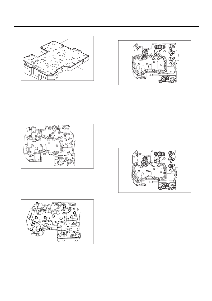
8) Install lower separate plate to lower valve body.
9) Temporarily assemble valve body.
NOTE:
Be careful not to drop the middle valve body and
upper body interior steel ball, or the lower body fil-
ter.
10) Tighten bolts.
NOTE:
Install the bolts (D) from upper valve body side.
Tightening torque:
8 N·m (0.8 kgf-m, 5.8 ft-lb)
11) Install the sensor, solenoids and duty solenoids
to specified positions.
12) Tighten the bolts and nuts.
Tightening torque:
8 N·m (0.8 kgf-m, 5.8 ft-lb)
(A) Lower separator plate
(B) Lower valve body
Bolt length mm (in)
(A) 40 (1.57)
(B) 62 (2.44)
(C) 73 (2.87)
(D) 79 (3.11)
AT-00076
( A )
( B )
AT-00077
AT-00904
B
B
B
B
D
C
B
B
D
A
A
A
(A) Lock-up duty solenoid (Blue)
(B) Low clutch timing solenoid (Gray)
(C) Line pressure duty solenoid (Red)
(D) Shift solenoid 1 (Yellow)
(E) Shift solenoid 2 (Green)
(F) 2-4 brake timing solenoid (Black)
(G) 2-4 brake duty solenoid (Red)
(H) SPORT shift solenoid (Beige) (if equipped)
Bolt length mm (in)
(A) 12 (0.47)
(B) 40 (1.57)
(C) 45 (1.77)
(D) 62 (2.44)
(E) 73 (2.87)
AT-00903
( A )
( B )
( C )
( D )
( E )
( F )
( G )
( H )
AT-00905
A
B
C
B
C
D
D
D
D
E
E
E
Нет комментариевНе стесняйтесь поделиться с нами вашим ценным мнением.
Текст