Subaru Legacy III (2000-2003 year). Service manual — part 541
AT-58
AUTOMATIC TRANSMISSION
REAR VEHICLE SPEED SENSOR
14.Rear Vehicle Speed Sensor
A: REMOVAL
When removing the rear vehicle speed sensor, re-
fer to “Front Vehicle Speed Sensor.” <Ref. to AT-
54, REMOVAL, Front Vehicle Speed Sensor.>
B: INSTALLATION
When installing the rear vehicle speed sensor, refer
to “Front Vehicle Speed Sensor.” <Ref. to AT-56,
INSTALLATION, Front Vehicle Speed Sensor.>
AT-59
AUTOMATIC TRANSMISSION
TORQUE CONVERTER TURBINE SPEED SENSOR
15.Torque Converter Turbine
Speed Sensor
A: REMOVAL
When removing the torque converter turbine speed
sensor, refer to “Front Vehicle Speed Sensor.”
<Ref. to AT-54, REMOVAL, Front Vehicle Speed
Sensor.>
B: INSTALLATION
When installing the torque converter turbine speed
sensor, refer to “Front Vehicle Speed Sensor.”
<Ref. to AT-56, INSTALLATION, Front Vehicle
Speed Sensor.>
AT-60
AUTOMATIC TRANSMISSION
CONTROL VALVE BODY
16.Control Valve Body
A: REMOVAL
1) Lift-up the vehicle.
2) Clean the transmission exterior.
3) Drain the ATF completely.
NOTE:
• Tighten the ATF drain plug after draining the
ATF.
• Replace the gasket with a new one.
Tightening torque:
25 N·m (2.5 kgf-m, 18.1 ft-lb)
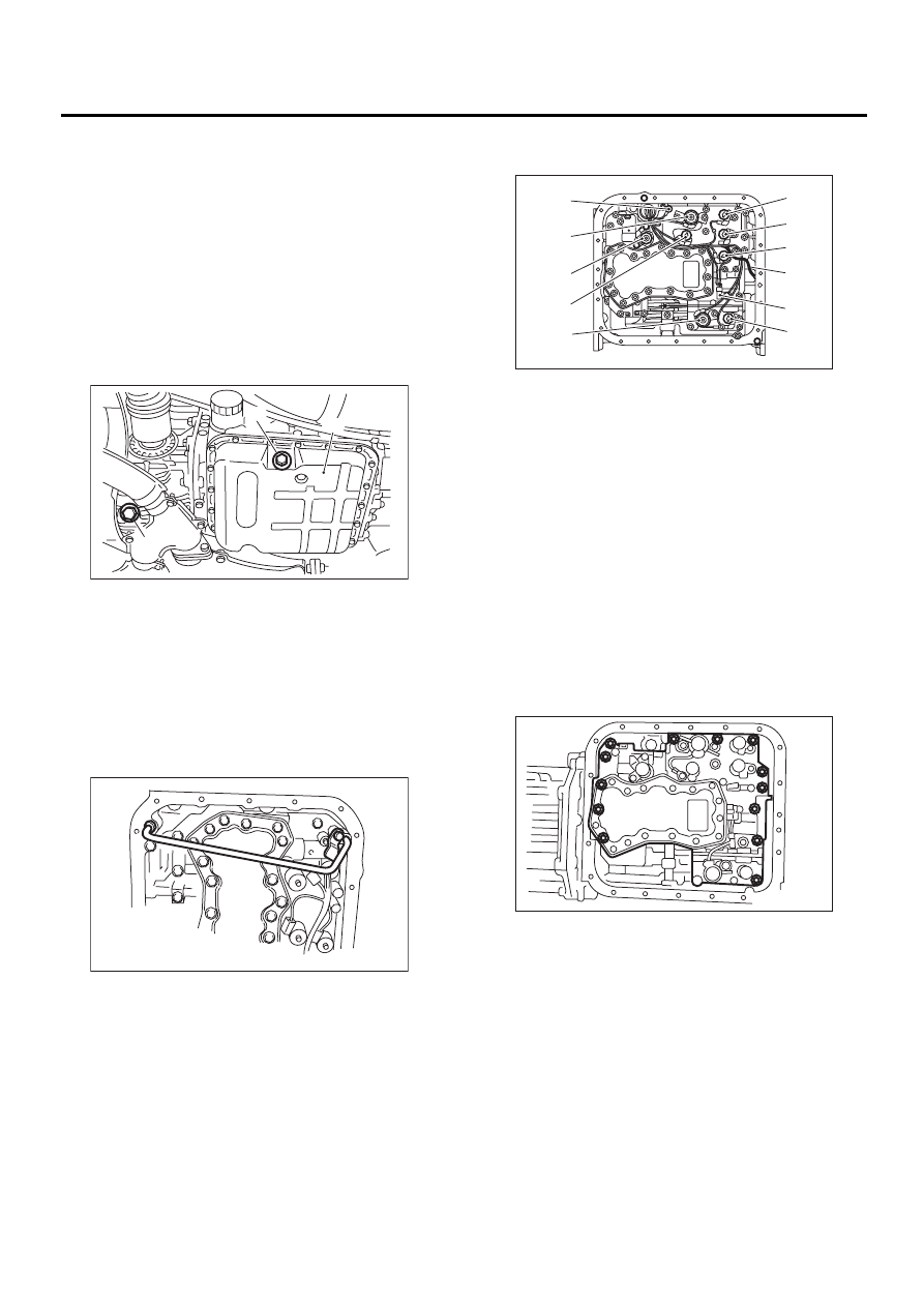
4) Remove the oil pan.
5) Remove and clean the magnet.
6) Remove the old gasket on the oil pan and trans-
mission case completely.
7) Remove the pipe. (TURBO model)
8) Disconnect each solenoid connector and re-
move ATF temperature sensor from control valve.
9) Remove the control valve.
NOTE:
When removing the control valve body, be careful
not to interfere with transfer duty solenoid wiring.
(A) Oil pan
(B) Drain plug
(C) Differential oil drain plug
AT-00016
( A )
( B )
( C )
AT-00801
(A) Lock-up duty solenoid (Blue)
(B) Transmission ground
(C) Line pressure duty solenoid (Red)
(D) Shift solenoid 2 (Yellow)
(E) Shift solenoid 1 (Green)
(F) 2-4 brake timing solenoid (Black)
(G) 2-4 brake duty solenoid (Red)
(H) ATF temperature sensor
(I) Transfer duty solenoid (Brown)
(J) Low clutch timing solenoid (Gray)
(K) Sport shift solenoid (Beige) (if equipped)
AT-00695
( A )
( B )
( C )
( D )
( E )
( F )
( H )
( J )
( G )
( K )
( I )
AT-00054
AT-61
AUTOMATIC TRANSMISSION
CONTROL VALVE BODY
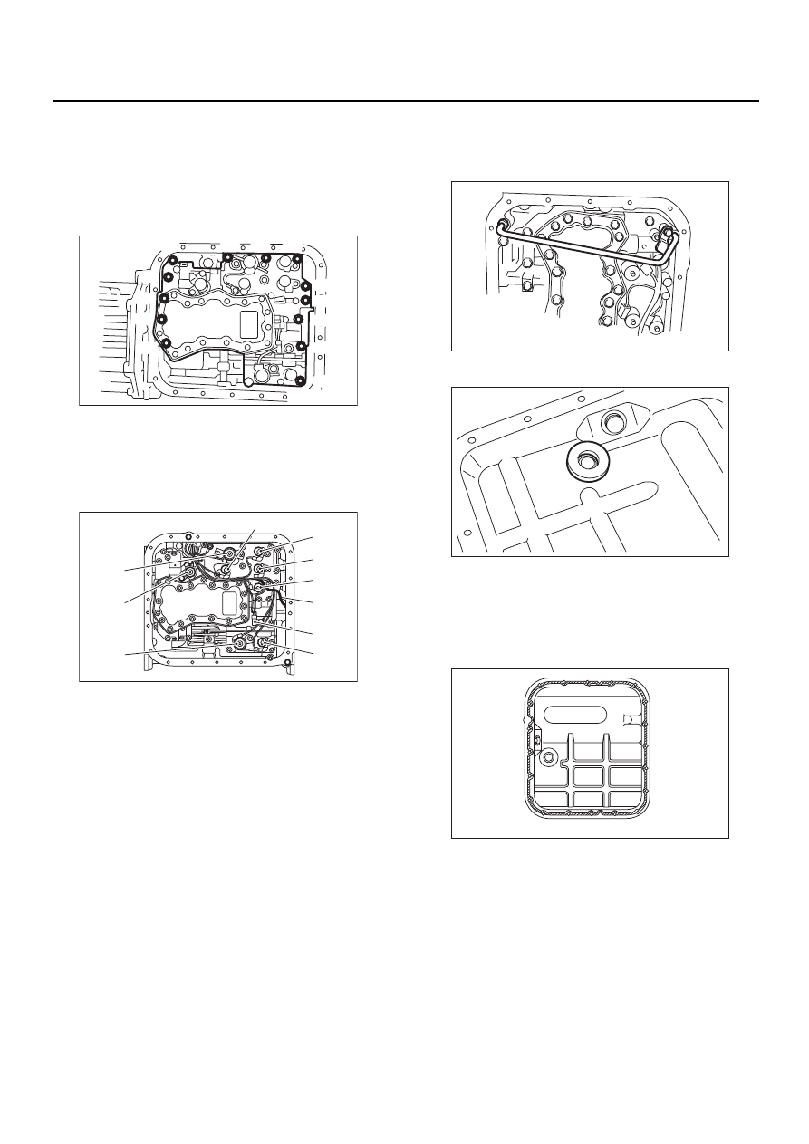
B: INSTALLATION
1) Set the range select lever in “N” range.
2) Install the control valve, ATF temperature sensor
and ground connectors.
Tightening torque:
8 N·m (0.8 kgf-m, 5.8 ft-lb)
3) Connect all connectors.
4) Install the pipe. (TURBO model)
Tightening torque:
8 N·m (0.8 kgf-m, 5.8 ft-lb)
5) Attach the magnet at specified position.
6) Apply proper amount of liquid gasket to the en-
tire oil pan mating surface.
Liquid gasket:
THREE BOND 1217B (Part No.
K0877YA020)
Bolt length mm (in)
(A) 30 (1.18)
(B) 55 (2.17)
(A) Lock-up duty solenoid (Blue)
(B) Low clutch timing solenoid (Gray)
(C) Line pressure duty solenoid (Red)
(D) Shift solenoid 2 (Yellow)
(E) Shift solenoid 1 (Green)
(F) 2-4 brake timing solenoid (Black)
(G) 2-4 brake duty solenoid (Red)
(H) ATF temperature sensor
(I) Transfer duty solenoid (Brown)
(J) Sport shift solenoid (Beige) (if equipped)
AT-00062
( A )
( A )
( A )
( A )
( A )
( A )
( A )
( A )
( B )
( B )
( B )
( B )
( B )
AT-00902
( A )
( B )
( C )
( D )
( E )
( F )
( H )
( G )
( J )
( I )
AT-00801
AT-00057
AT-00051
Нет комментариевНе стесняйтесь поделиться с нами вашим ценным мнением.
Текст