Subaru Legacy III (2000-2003 year). Service manual — part 838
PS-40
POWER ASSISTED SYSTEM (POWER STEERING)
STEERING GEARBOX [LHD MODEL]
19) Install lock washers and tighten left and right
tie-rods into rack ends.Tightening torque:
78 N·m (8.0 kgf-m, 58 ft-lb)
20) Bend lock washer, using chisel.
CAUTION:
Be careful not to scratch rack when bending
lock washer.
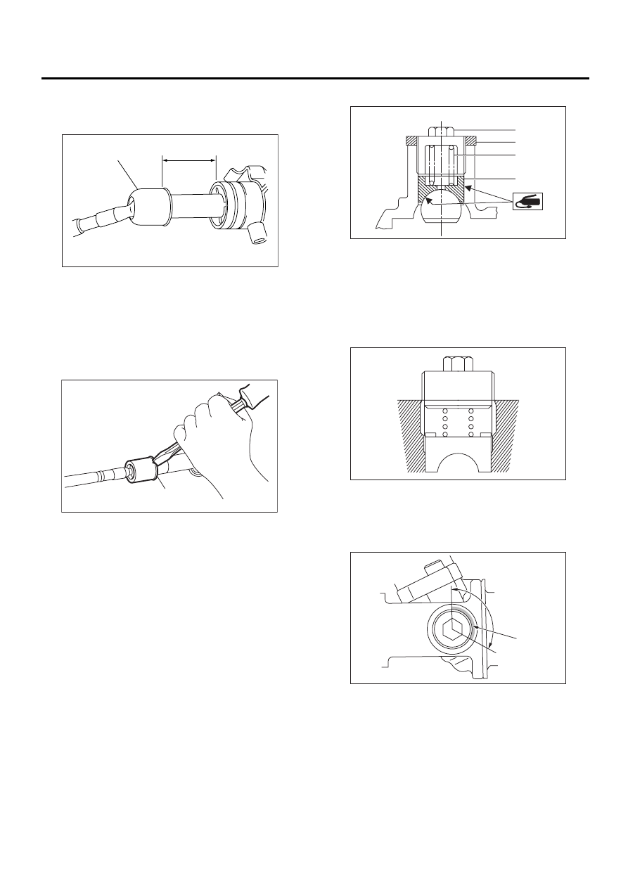
21) Rack and pinion backlash adjustment
(1) Loosen adjusting screw.
(2) Rotate input shaft so that rack is in the
straight ahead direction.
(3) Apply grease to sleeve.
(4) Tighten adjusting screw by approx. two
threads.
(5) Apply liquid packing to at least 1/3 of entire
perimeter of adjusting screw thread.
Liquid packing:
THREE BOND 1141
(6) Tighten adjusting screw to 7.4 N·m (0.75
kgf-m, 5.4 ft-lb) and back off 25
°
.
(7) Install lock nut. While holding adjusting
screw with a wrench, tighten lock nut using ST.
ST
926230000
SPANNER
(1) Tie-rod
(2) Approx. 40 mm (1.57 in)
(1) Lock washer
PS-00091
(2)
(1)
PS-00212
( 1 )
(1) Adjusting screw
(2) Lock nut
(3) Spring
(4) Sleeve
(1) Apply liquid packing to at least 1/3 of entire
perimeter.
PS-00213
( 1 )
( 2 )
( 3 )
( 4 )
PS-00214
PS-00092
( 1 )
PS-41
POWER ASSISTED SYSTEM (POWER STEERING)
STEERING GEARBOX [LHD MODEL]
Tightening torque (Lock nut):
39 N·m (4.0 kgf-m, 29 ft-lb)
NOTE:
• Hold adjusting screw with a wrench to prevent it
from turning while tightening lock nut.
• Make adjustment so that steering wheel can be
rotated fully from lock to lock without binding.
22) Inspect for service limit as per article of “Ser-
vice limit”. <Ref. to PS-47, SERVICE LIMIT, IN-
SPECTION, Steering Gearbox [LHD MODEL].>
Make replacement and adjustment if necessary.
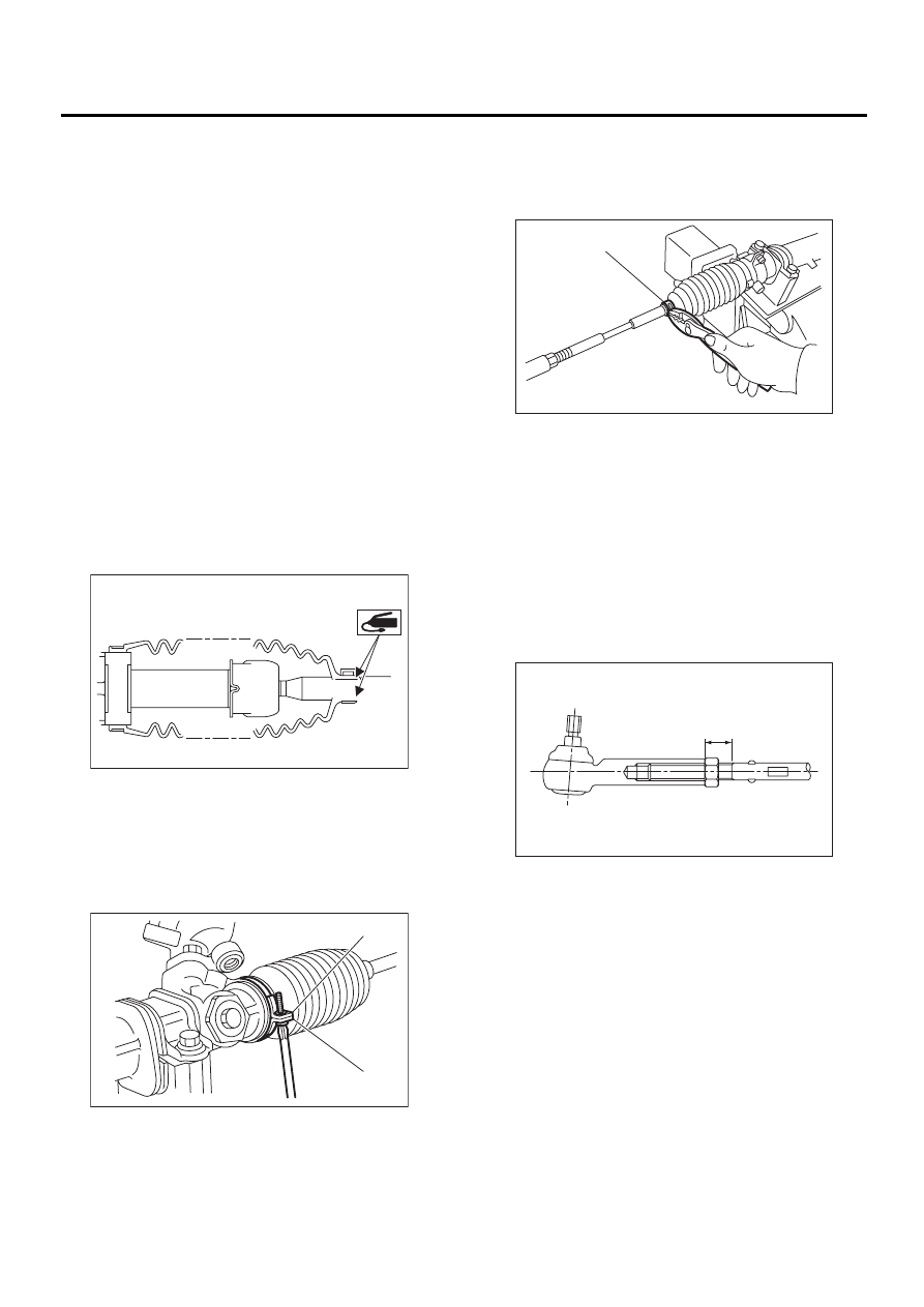
23) Install boot to housing.
NOTE:
• Before installing boot, be sure to apply grease to
the groove of tie-rod.
• Install fitting portions of boots to the following
portions in both sides of assembled steering gear-
box.
The groove on gearbox
The groove on the rod
• Make sure that boot is installed without unusual
inflation or deflation.
24) Using a screwdriver, tighten the screw until the
ends “A” and “B” of the band come into contact with
each other.
NOTE:
Always tighten the band from the underside of the
gear box.
25) Fix boot end with clip (small).
CAUTION:
After installing, check boot end is positioned
into groove on tie-rod.
26) If tie-rod end was removed, screw in lock nut
and tie-rod end to screwed portion of tie-rod, and
tighten lock nut temporarily in a position as shown
in figure.
Installed tie-rod length: L
15 mm (0.59 in)
NOTE:
Pay attention to difference between right and left
tie-rod ends.
PS-00283
PS-00284
( B )
( A )
(1) Clip
PS-00048
( 1 )
PS-00097
L
PS-42
POWER ASSISTED SYSTEM (POWER STEERING)
STEERING GEARBOX [LHD MODEL]
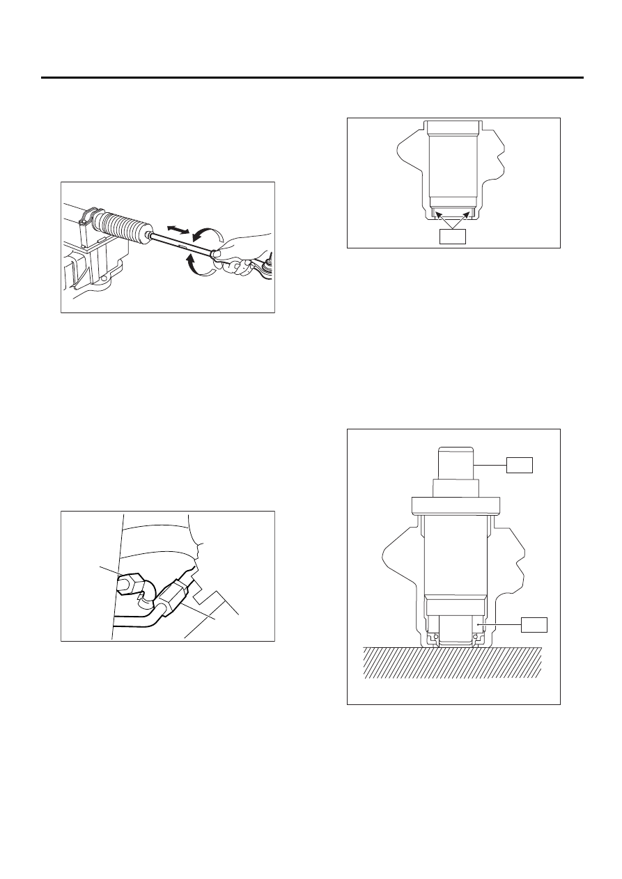
27) Inspect gearbox as follows:
“A” Holding tie-rod end, repeat lock to lock two or
three times as quickly as possible.
“B” Holding tie-rod end, turn it slowly at a radius one
or two times as large as possible.
After all, make sure that boot is installed in the
specified position without deflation.
28) Remove gearbox from ST.
ST
926200000
STAND
29) Install four pipes on gearbox.
(1) Connect pipes A and B to four pipe joints of
gearbox. Connect upper pipe B first, and lower
pipe A.
Tightening torque:
13 N·m (1.3 kgf-m, 9.4 ft-lb)
(2) Connect pipes C and D to gearbox.
Connect lower pipe C first, and upper pipe D
second.
Tightening torque:
15 N·m (1.5 kgf-m, 10.8 ft-lb)
2. CONTROL VALVE ASSEMBLY
Specified steering grease:
VALIANT GREASE M2 (Part No.
003608001)
1) Clean all parts and tools before reassembling.
2) Apply a coat of specified power steering fluid to
inner wall of valve housing.
3) Attach ST2 to ST1, and press oil seal into place
using a press.
ST1
34099FA120 INSTALLER & REMOVER
SEAL
ST2
34099FA130 INSTALLER SEAL
(1) Face oil seal in the direction shown in figure
when installing.
(2) To avoid scratching oil seal, apply a coat of
grease to contact surface of installer and oil
seal.
(3) To facilitate installation, attach oil seal to in-
staller and position in valve housing before
pressing into place.
4) Put vinyl tape around pinion shaft splines to pro-
tect oil seal from damage.
(1) Pipe C
(2) Pipe D
PS-00098
A
B
( 1 )
( 2 )
PS-00205
PS-00285
Fluid
PS-00286
ST1
ST2
PS-43
POWER ASSISTED SYSTEM (POWER STEERING)
STEERING GEARBOX [LHD MODEL]
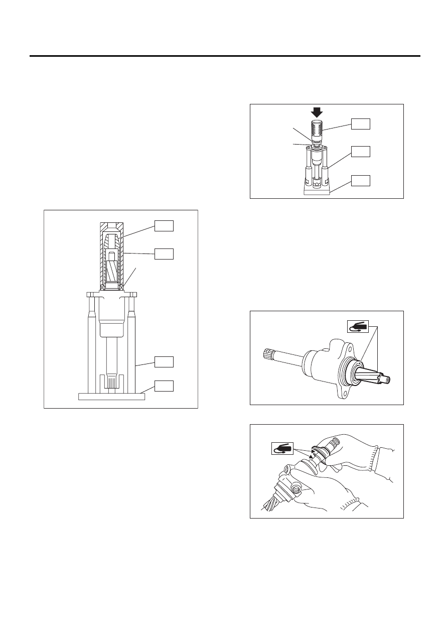
5) Fit pinion and valve assembly into valve hous-
ing.
NOTE:
Apply specified power steering fluid to outer diam-
eter surface of input shaft and outer surface of
valve body seal ring, and pay special attention not
to damage seal when inserting pinion and valve as-
sembly.
6) Secure valve assembly to ST1 and ST2.
7) Put ST3 over pinion, and insert oil seal, then
force-fit oil seal into housing using ST4.
ST1
926370000
INSTALLER A
ST2
927630000
STAND BASE
ST3
926360000
INSTALLER A
ST4
927620000
INSTALLER B
NOTE:
• Apply specified power steering fluid to oil seal
and ST3, being careful not to damage oil seal lip.
• Push oil seal until ST3 contacts housing end
face.
8) Remove ST3, and fit backing washer.
9) Force-fit ball bearing using ST3.
ST1
926370000
INSTALLER A
ST2
34099FA100 STAND BASE
ST3
927640000
INSTALLER B
NOTE:
Be careful not to tilt ball bearing during installation.
10) Install snap ring using snap ring pliers.
NOTE:
Rotate snap ring to check for proper installation.
11) Apply genuine grease to pinion gear and bear-
ing of valve assembly.
12) Apply specified grease to dust cover.
13) Install dust cover on valve assembly.
(1) Oil seal
PS-00172
( 1 )
ST3
ST4
ST1
ST2
(1) Ball bearing
(2) Backing washer
PS-00173
( 1 )
( 2 )
ST3
ST1
ST2
PS-00165
PS-00282
Нет комментариевНе стесняйтесь поделиться с нами вашим ценным мнением.
Текст