Subaru Legacy III (2000-2003 year). Service manual — part 839
PS-44
POWER ASSISTED SYSTEM (POWER STEERING)
STEERING GEARBOX [LHD MODEL]
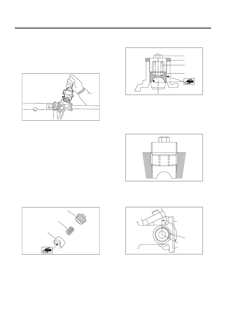
14) Install gasket on valve assembly. Insert valve
assembly into place while facing rack teeth toward
pinion.
CAUTION:
Be sure to use a new gasket.
NOTE:
Do not allow packing to be caught when installing
valve assembly.
15) Tighten bolts alternately to secure valve as-
sembly.
Tightening torque:
25 N·m (2.5 kgf-m, 18.1 ft-lb)
CAUTION:
Be sure to alternately tighten bolts.
16) Apply grease to sleeve insertion hole.
17) Apply grease to dust seal insertion hole.
CAUTION:
Apply clean grease with clean hands. If material
having a sharp edge is used for applying
grease, oil seal at the inside might be damaged.
18) Apply grease to sliding surface of sleeve and
spring seat, then insert sleeve into pinion housing.
Fit spring into sleeve screw, pack grease inside of
screw, then install the screw.
19) Rack and pinion backlash adjustment
(1) Loosen adjusting screw.
(2) Rotate input shaft so that rack is in the
straight ahead direction.
(3) Apply grease to sleeve.
(4) Tighten adjusting screw by approx. two
threads.
(5) Apply liquid packing to at least 1/3 of entire
perimeter of adjusting screw thread.
Liquid packing:
THREE BOND 1141
(6) Tighten adjusting screw to 7.4 N·m (0.75
kgf-m, 5.4 ft-lb) and back off 25
°
.
(1) Adjusting screw
(2) Spring
(3) Sleeve
PS-00117
PS-00211
( 1 )
( 2 )
( 3 )
(1) Adjusting screw
(2) Lock nut
(3) Spring
(4) Sleeve
(1) Apply liquid packing to at least 1/3 of entire
perimeter.
PS-00213
( 1 )
( 2 )
( 3 )
( 4 )
PS-00214
PS-00092
( 1 )
PS-45
POWER ASSISTED SYSTEM (POWER STEERING)
STEERING GEARBOX [LHD MODEL]
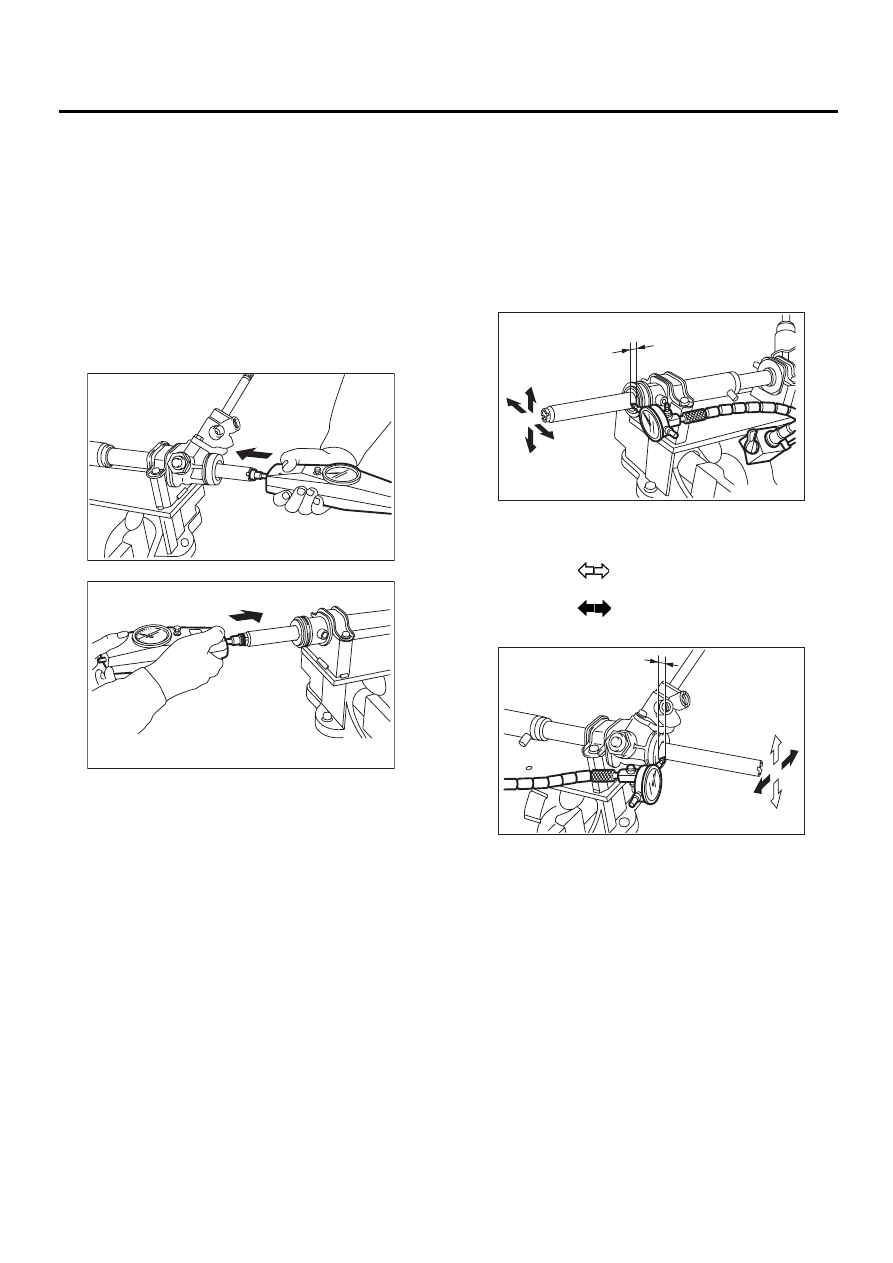
(7) Install lock nut. While holding adjusting
screw with a wrench, tighten lock nut using ST.
ST
926230000
SPANNER
Tightening torque (Lock nut):
39 N·m (4.0 kgf-m, 29 ft-lb)
NOTE:
• Hold adjusting screw with a wrench to prevent it
from turning while tightening lock nut.
• Make adjustment so that steering wheel can be
rotated fully from lock to lock without binding.
20) Check for service limit as per article of “Service
limit”. <Ref. to PS-47, SERVICE LIMIT, INSPEC-
TION, Steering Gearbox [LHD MODEL].> Make
replacement and adjustment if necessary.
PS-46
POWER ASSISTED SYSTEM (POWER STEERING)
STEERING GEARBOX [LHD MODEL]
E: INSPECTION
1. BASIC INSPECTION
1) Clean all disassembled parts, and check for wear, damage, or any other faults, then repair or replace as
necessary.
2) When disassembling, check inside of gearbox for water. If any water is found, carefully check boot for
damage, input shaft dust seal, adjusting screw and boot clips for poor sealing. If faulty, replace with new
parts.
No.
Parts
Inspection
Corrective action
1
Input shaft
(1) Bend of input shaft
(2) Damage on serration
If bend or damage is excessive, replace entire gearbox.
2
Dust seal
(1) Crack or damage
(2) Wear
If outer wall slips, lip is worn out or damage is found,
replace it with new one.
3
Rack and pinion
Poor mating of rack with pinion
(1) Adjust backlash properly.
By measuring turning torque of gearbox and sliding resis-
tance of rack, check if rack and pinion engage uniformly
and smoothly with each other. (Refer to “Service limit”.)
(2) Keeping rack pulled out all the way so that all teeth
emerge, check teeth for damage.
Even if abnormality is found in either (1) or (2), replace
entire gearbox.
4
Gearbox unit
(1) Bend of rack shaft
(2) Bend of cylinder portion
(3) Crack or damage on cast iron
portion
Replace gearbox with new one.
(4) Wear or damage on rack bush
If free play of rack shaft in radial direction is out of the
specified range, replace gearbox with new one. (Refer to
“Service limit”.)
(5) Wear on input shaft bearing
If free plays of input shaft in radial and axial directions are
out of the specified ranges, replace gearbox with new
one. (Refer to “Service limit”.)
5
Boot
Crack, damage or deterioration
Replace.
6
Tie-rod
(1) Looseness of ball joint
(2) Bend of tie-rod
Replace.
7
Tie-rod end
Damage or deterioration on dust
seal
Replace.
8
Adjusting screw
spring
Deterioration
Replace.
9
Boot clip
Deterioration
Replace.
10
Sleeve
Damage
Replace.
11
Pipes
(1) Damage to flared surface
(2) Damage to flare nut
(3) Damage to pipe
Replace.
PS-47
POWER ASSISTED SYSTEM (POWER STEERING)
STEERING GEARBOX [LHD MODEL]
2. SERVICE LIMIT
Make a measurement as follows. If it exceeds the
specified service limit, adjust or replace.
NOTE:
When making a measurement, vise gearbox by us-
ing ST. Never vise gearbox by inserting aluminum
plates, etc. between vise and gearbox.
ST
926200000
STAND
Sliding resistance of rack shaft:
Service limit
304 N (31 kgf, 68 lb) or less
3. RACK SHAFT PLAY IN RADIAL DIREC-
TION
Right-turn steering:
Service limit
0.19 mm (0.0075 in) or less
On condition
L: 5 mm (0.20 in)
P: 122.6 N (12.5 kgf, 27.6 lb)
Left-turn steering:
Service limit
Direction
0.3 mm (0.012 in) or less
Direction
0.15 mm (0.0059 in) or less
PS-00099
PS-00100
PS-00101
L
P
PS-00102
5 mm (0.20 in)
98 N
(10 kgf, 22 lb)
Нет комментариевНе стесняйтесь поделиться с нами вашим ценным мнением.
Текст