Subaru Legacy III (2000-2003 year). Service manual — part 970
SL-36
SECURITY AND LOCKS
IMMOBILIZER CONTROL MODULE
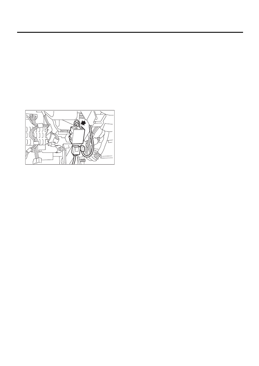
20.Immobilizer Control Module
A: REMOVAL
NOTE:
The following positions for removal and installation
are for LHD models. The positions for RHD models
are symmetrically opposite.
1) Disconnect ground cable from battery.
2) Remove instrument panel lower cover. <Ref. to
EI-35, REMOVAL, Instrument Panel Assembly.>
3) Disconnect connector from immobilizer control
module.
4) Remove immobilizer control module.
B: INSTALLATION
Install in the reverse order of removal.
SL-00121
SL-37
SECURITY AND LOCKS
IMMOBILIZER ANTENNA
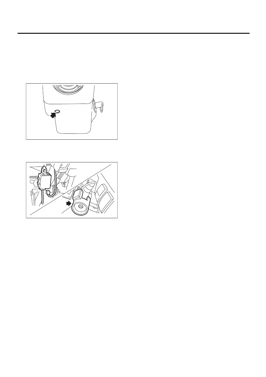
21.Immobilizer Antenna
A: REMOVAL
1) Disconnect ground cable from battery.
2) Remove instrument panel lower cover. <Ref. to
EI-35, REMOVAL, Instrument Panel Assembly.>
3) Remove screws, separate upper column cover
and lower column cover.
4) Disconnect immobilizer antenna connector (A)
from immobilizer control module.
5) Remove immobilizer antenna (B).
B: INSTALLATION
Install in the reverse order of removal.
SL-00122
SL-00170
( A )
( B )
SL-38
SECURITY AND LOCKS
KEYLESS ENTRY CONTROL MODULE
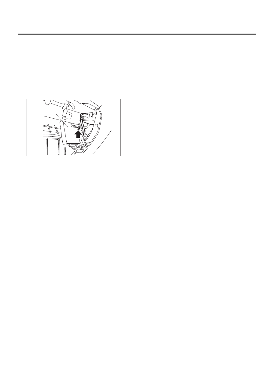
22.Keyless Entry Control Mod-
ule
A: REMOVAL
1) Disconnect ground cable from battery.
2) Remove glove box. <Ref. to EI-32, REMOVAL,
Glove Box.>
3) Remove nut, then remove keyless entry control
module (B) and the other electrical control module
(A) while disconnecting connector.
4) Disconnect keyless entry control module and the
other electrical control module.
B: INSTALLATION
Install in the reverse order of removal.
SL-00102
( A )
( B )
SL-39
SECURITY AND LOCKS
KEYLESS TRANSMITTER
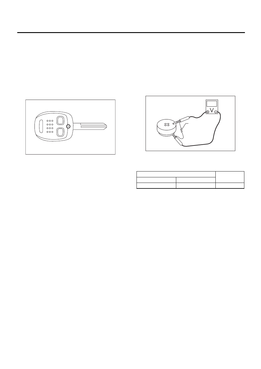
23.Keyless Transmitter
A: REMOVAL
1. TRANSMITTER BATTERY
Remove battery from transmitter.
NOTE:
To prevent static electricity damage to transmitter
printed circuit board, touch steel area of building
with hand to discharge static electricity carried on
body or clothes before disassembling transmitter.
B: INSTALLATION
1. TRANSMITTER BATTERY
Install in the reverse order of removal.
C: INSPECTION
1. TRANSMITTER BATTERY
1) Measure voltage between battery (+) terminal
and (–) terminal.
NOTE:
• Battery discharge occurs during measurement.
Complete measurement within 5 seconds.
• During battery voltage measurement, voltage
falls more than 1.8 volts in 3 seconds period.
If NG, replace the battery. (Use CR1620 or equiva-
lent.)
D: REPLACEMENT
1. TRANSMITTER REGISTRATION
NOTE:
A maximum of 3 transmitters can be registered for
each individual vehicle.
1) Remove the side sill cover at the driver's side,
then connect the registration connectors at the
front pillar lower section.
2) Unlock the door lock.
3) Press any button of the transmitter twice to be
registered.
4) The door lock will automatically lock and unlock
in sequence. This indicates the completion of trans-
mitter registration for the first transmitter.
5) If registration of another transmitter is now to be
carried out, repeat procedure 3) and 4).
6) Disconnect the registration connectors after the
completion of all registration operations. After con-
firming the operation of the door lock using the
newly registered transmitter(s), reinstall the side sill
cover at the driver's side.
SL-00124
(A) Resistance 47
Ω
Tester connection
Standard
(+)
(–)
Battery (+) terminal
Battery (–) terminal
More than 2V
SL-00125
( A )
Нет комментариевНе стесняйтесь поделиться с нами вашим ценным мнением.
Текст