Subaru Legacy III (2000-2003 year). Service manual — part 989
EB-8
EXTERIOR BODY PANELS
GENERAL DESCRIPTION
C: PREPARATION TOOL
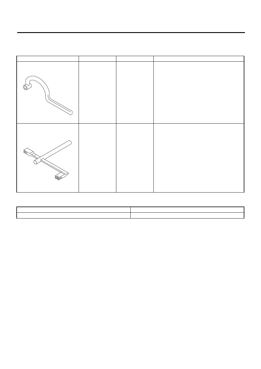
1. SPECIAL TOOLS
2. GENERAL TOOL
ILLUSTRATION
TOOL NUMBER
DESCRIPTION
REMARKS
925610000
WRENCH
Used for removing and installing door hinge.
927780000
REMOVER
Used for removing and installing trunk torsion bar.
TOOL NAME
REMARKS
Support Jack
Used for supporting door panel.
ST-925610000
ST-927780000
EB-9
EXTERIOR BODY PANELS
FRONT HOOD
2. Front Hood
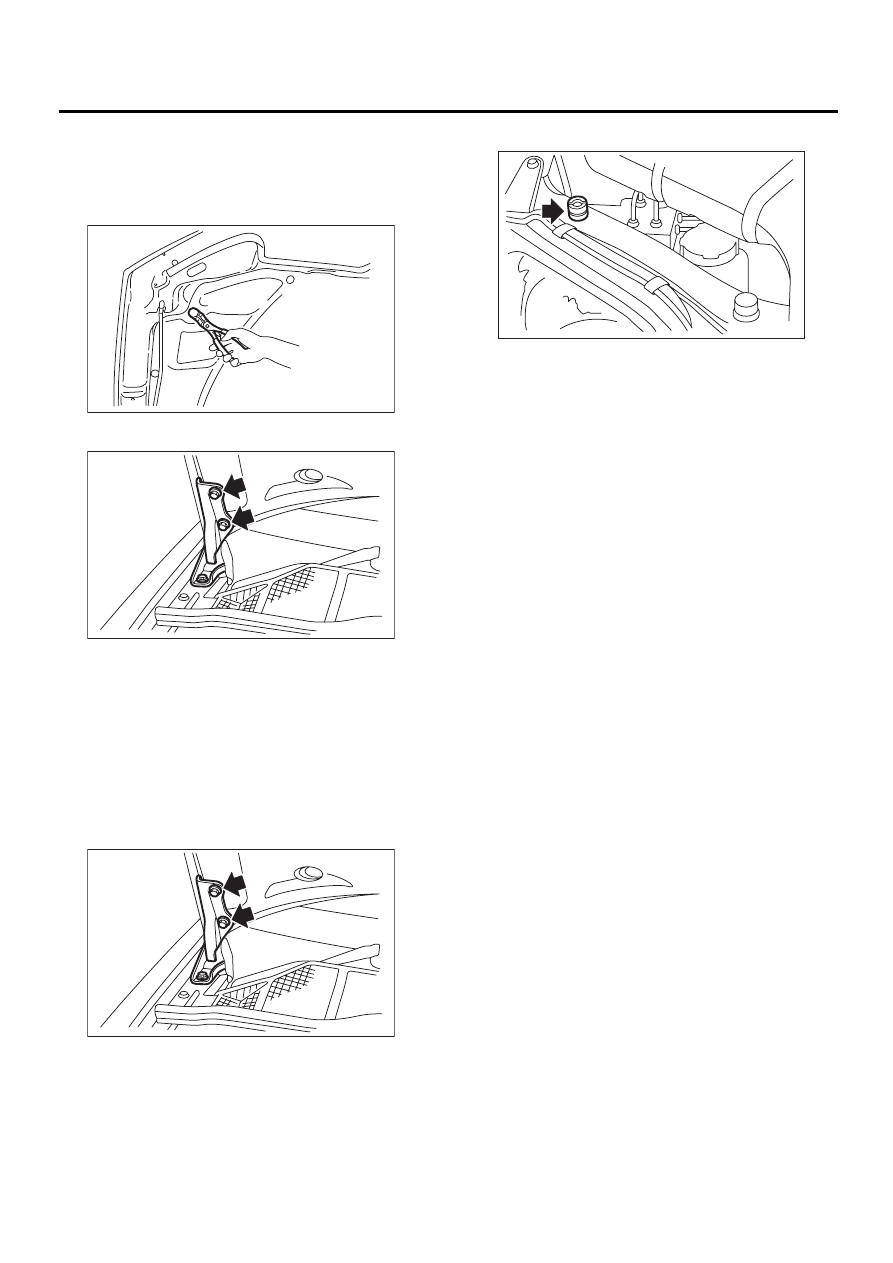
A: REMOVAL
1) Open front hood to remove washer nozzles.
2) Remove clips to remove hood insulator.
3) Remove bolts to disconnect hood from hinges.
B: INSTALLATION
1) Install in the reverse order of removal.
2) Adjust clearance between hood and fender.
Clearance must be equal at both sides.
Tightening torque:
24.5 N·m (2.5 kgf-m, 18 ft-lb)
C: ADJUSTMENT
1) Use hinge mounting holes to align front hood
longitudinally and laterally.
2) Adjust height at front end of hood. <Ref. to SL-
31, REMOVAL, Front Hood Lock Assembly.>
3) Rotate front hood buffer to adjust lateral height.
EB-00046
EB-00047
EB-00047
EB-00049
EB-10
EXTERIOR BODY PANELS
FENDER PANEL
3. Fender Panel
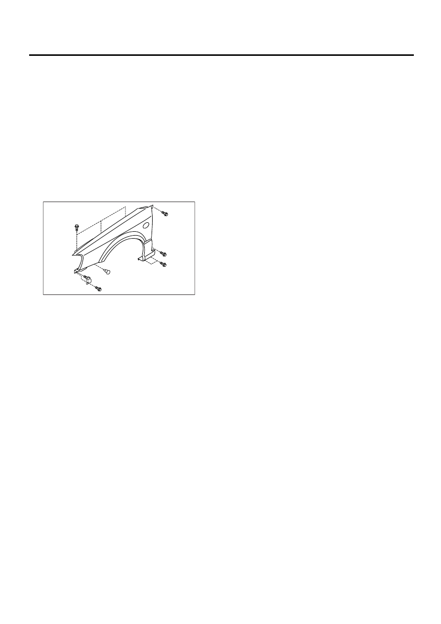
A: REMOVAL
1) Disconnect ground cable from battery.
2) Remove side sill spoilers. <Ref. to EI-29, RE-
MOVAL, Side Sill Spoiler.>(If fitted)
3) Remove side protectors and fender protectors.
(OUTBACK)
4) Remove front bumper face. <Ref. to EI-14, RE-
MOVAL, Front Bumper.>
5) Remove headlights. <Ref. to LI-15, REMOVAL,
Headlight Assembly.>
6) Remove mud guard. <Ref. to EI-22, REMOVAL,
Mud Guard.>
7) Remove bolts and clips to remove front fender.
B: INSTALLATION
1) Install in the reverse order of removal.
2) When fender panel is installed, clearance be-
tween fender panel and hood or front fender must
be equal.
Tightening torque:
7.35 N·m (0.75 kgf-m, 5.4 ft-lb)
EB-00050
EB-11
EXTERIOR BODY PANELS
FRONT DOOR PANEL
4. Front Door Panel
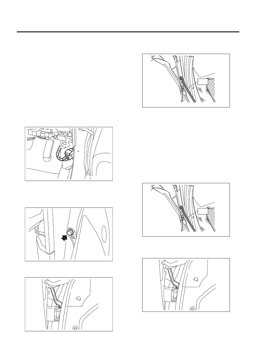
A: REMOVAL
1) Disconnect ground cable from battery.
2) Remove front door trim. <Ref. to EI-30, RE-
MOVAL, Front Door Trim.>
3) Remove outer mirror assembly. <Ref. to GW-
33, REMOVAL, Outer Mirror Assembly.>
4) Remove front door regulator and motor. <Ref. to
GW-16, REMOVAL, Front Regulator and Motor As-
sembly.>
5) Remove front door latch assembly. <Ref. to SL-
21, REMOVAL, Front Door Latch Assembly.>
6) Remove front outer handle. <Ref. to SL-20, RE-
MOVAL, Front Outer Handle.>
7) Remove front pillar lower trim to disconnect con-
nector from body harness.
8) Put wooden block on jack and place jack under
door. Support door with a jack to protect it from
damage.
9) Remove checker bolts.
10) Remove door-side bolts for upper and lower
hinges to remove door.
11) Using special tool, remove body-side bolts for
upper and lower hinges, and remove door hinges.
ST
925610000
DOOR HINGE WRENCH
B: INSTALLATION
1) Install in the reverse order of removal.
2) Apply grease to sliding area of door hinges.
Tightening torque:
Refer to COMPONENT in General Descrip-
tion. <Ref. to EB-4, FRONT DOOR PANEL,
COMPONENT, General Description.>
C: ADJUSTMENT
1) Using special tool, loosen body-side bolts of up-
per and lower hinges to align the position of front
door panel longitudinally and vertically.
ST
925610000
DOOR HINGE WRENCH
2) Loosen door-side bolts of upper and lower hing-
es to align the position of front door panel vertically
and laterally at the front end.
EB-00051
EB-00052
EB-00053
EB-00054
ST
EB-00054
ST
EB-00053
Нет комментариевНе стесняйтесь поделиться с нами вашим ценным мнением.
Текст