Subaru Legacy III (2000-2003 year). Service manual — part 688
DS-30
DRIVE SHAFT SYSTEM
FRONT DRIVE SHAFT
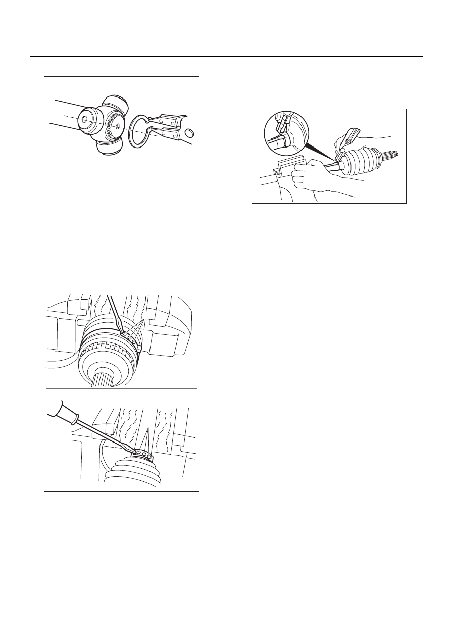
9) Remove snap ring and trunnion.
CAUTION:
Be sure to wrap shaft splines with vinyl tape to
prevent boot from scratches.
10) Remove SFJ boot.
11) Place drive shaft in a vise between wooden
blocks.
CAUTION:
Do not place drive shaft directly in the vise; use
wooden block.
12) Raise boot band claws by means of screwdriv-
er and hammer.
13) Cut and remove the boot.
CAUTION:
The boot must be replaced with a new one
whenever it is removed.
14) Disassembly of axle is completed at steps
above because BJ cannot be disassembled.
(A) Boot band claws
DS-00111
DS-00112
( A )
( A )
DS-00113
DS-31
DRIVE SHAFT SYSTEM
FRONT DRIVE SHAFT
D: ASSEMBLY
CAUTION:
Use specified grease.
BJ side:
NTG2218 (Part No. 28093AA000)
SFJ side:
SSG6003 (Part No. 28093TA000)
1) Place BJ boot and small boot band on BJ side of
shaft.
CAUTION:
Be sure to wrap shaft splines with vinyl tape to
prevent boot from scratches.
2) Place drive shaft in a vise.
CAUTION:
Do not place drive shaft directly in the vise; use
wooden blocks.
3) Apply a coat of specified grease [60 to 70 g (2.12
to 2.47 oz)] to BJ.
4) Apply an even coat of specified grease [20 to 30
g (0.71 to 1.06 oz)] to the entire inner surface of
boot. Also apply grease to shaft.
NOTE:
The inside of the larger end of BJ boot and the boot
groove shall be cleaned so as to be free from
grease and other substances.
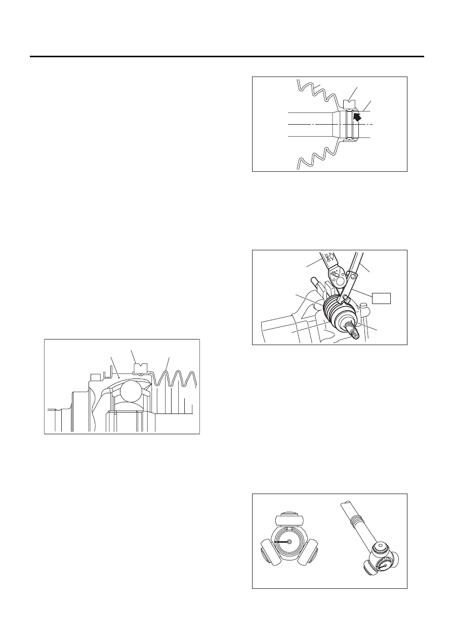
5) Install boot projecting portion to BJ groove.
6) Set large boot band in place.
7) Install boot projecting portion to shaft groove.
8) Tighten boot bands using ST, torque wrench and
socket flex handle.
ST
28099AC000
BOOT BAND PLIER
Tightening torque:
Large boot band
157 N·m (16.0 kgf-m, 116 ft-lb) or more
Small boot band
133 N·m (13.6 kgf-m, 98 ft-lb) or more
9) Place SFJ boot at the center of shaft.
10) Align alignment marks and install trunnion on
shaft.
(A) BJ
(B) Large boot band
(C) Boot
DS-00114
( A )
( B )
( C )
(A) Boot
(B) Small boot band
(C) Shaft
(A) Large boot band
(B) Boot
(C) Torque wrench
(D) Socket flex handle
(E) BJ
DS-00115
( A )
( B )
( C )
DS-00116
( A )
( B )
( C )
( D )
( E )
ST
DS-00110
DS-32
DRIVE SHAFT SYSTEM
FRONT DRIVE SHAFT
11) Install snap ring to shaft.
CAUTION:
Confirm that the snap ring is completely fitted
in the shaft groove.
12) Fill 100 to 110 g (3.53 to 3.88 oz) of specified
grease into the interior of SFJ outer race.
13) Apply a coat of specified grease to free ring and
trunnion.
14) Align alignment marks on free ring and trunnion
and install free ring.
CAUTION:
Be careful with the free ring position.
15) Align alignment marks on shaft and outer race,
and install outer race.
16) Install circlip in the groove on SFJ outer race.
CAUTION:
Pull the shaft lightly and assure that the circlip
is completely fitted in the groove.
17) Apply an even coat of the specified grease 30
to 40 g (1.06 to 1.41 oz) to the entire inner surface
of boot.
18) Install SFJ boot taking care not to twist it.
CAUTION:
• The inside of the larger end of SFJ boot and
the boot groove shall be cleaned so as to be
free from grease and other substances.
• When installing SFJ boot, position outer race
of SFJ at center of its travel.
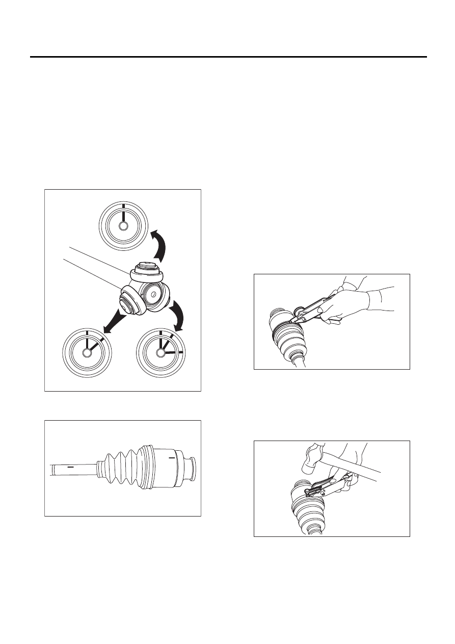
19) Put a band through the clip and wind twice in
alignment with band groove of boot.
CAUTION:
Use a new band.
20) Pinch the end of band with pliers. Hold the clip
and tighten securely.
NOTE:
When tightening boot, exercise care so that the air
within the boot is appropriate.
21) Tighten band by using ST.
ST
925091000
BAND TIGHTENING TOOL
NOTE:
Tighten band until it cannot be moved by hand.
22) Tap on the clip with the punch provided at the
end of ST.
ST
925091000
BAND TIGHTENING TOOL
CAUTION:
Tap to an extent that the boot underneath is not
damaged.
DS-00109
DS-00158
DS-00132
DS-00133
DS-33
DRIVE SHAFT SYSTEM
FRONT DRIVE SHAFT
23) Cut off band with an allowance of about 10 mm
(0.39 in) left from the clip and bend this allowance
over the clip.
CAUTION:
Be careful so that the end of the band is in close
contact with clip.
24) Fix up boot on BJ in the same manner.
NOTE:
Extend and retract SFJ to provide equal grease
coating.
E: INSPECTION
Check the removed parts for damage, wear, corro-
sion etc. If faulty, repair or replace.
1) DOJ (Double Offset Joint)
Check seizure, corrosion, damage, wear and ex-
cessive play.
2) SFJ (Shudder-less Free-ring tripod Joint)
Check seizure, corrosion, damage and excessive
play.
3) Shaft
Check excessive bending, twisting, damage and
wear.
4) BJ (Bell Joint)
Check seizure, corrosion, damage and excessive
play.
5) Boot
Check for wear, warping, breakage or scratches.
6) Grease
Check for discoloration or fluidity.
Нет комментариевНе стесняйтесь поделиться с нами вашим ценным мнением.
Текст