Subaru Legacy III (2000-2003 year). Service manual — part 84
LU(H4SO)-10
LUBRICATION
OIL PUMP
4. Oil Pump
A: REMOVAL
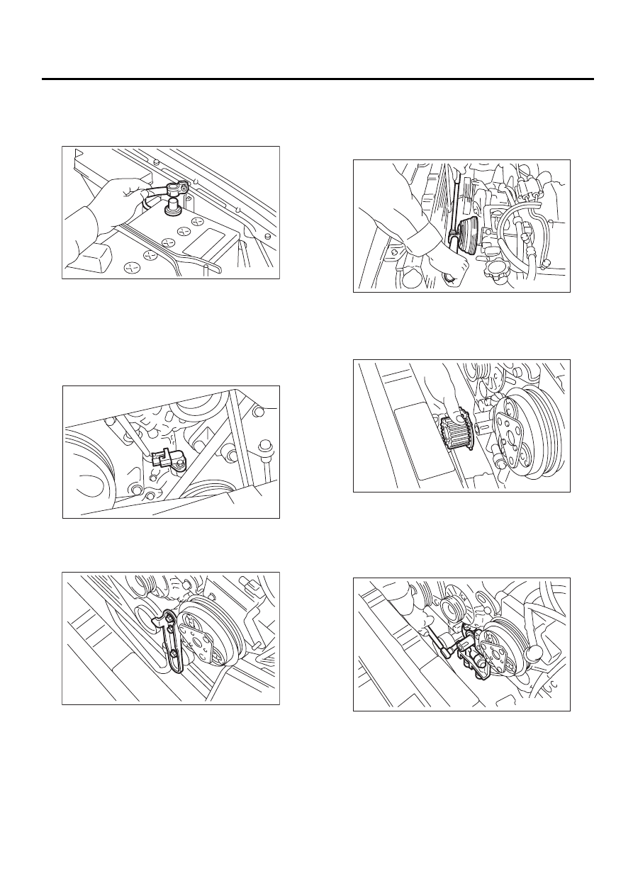
1) Disconnect battery ground cable.
2) Lift-up the vehicle.
3) Remove under cover. <Ref. to EI-13, REMOV-
AL, Front Under Cover.>
4) Lower the vehicle.
5) Remove radiator. <Ref. to CO(H4SO)-23, RE-
MOVAL, Radiator.>
6) Remove crankshaft position sensor.
7) Remove V-belts. <Ref. to ME(H4SO)-41, RE-
MOVAL, V-belt.>
8) Remove rear side V-belt tensioner.
9) Remove crankshaft pulley by using ST.
ST
499977100
CRANKSHAFT PULLEY
WRENCH (2500 cc model)
ST
499977400
CRANKSHAFT PULLEY
WRENCH (2000 cc model)
10) Remove water pump. <Ref. to CO(H4SO)-16,
REMOVAL, Water Pump.>
11) Remove timing belt guide. (MT vehicle)
12) Remove crankshaft sprocket.
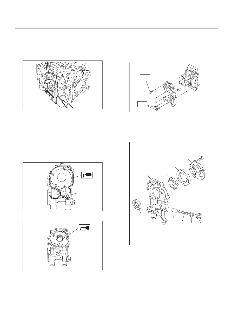
13) Remove bolts which install oil pump onto cylin-
der block.
NOTE:
To disassemble and check oil pump, loosen relief
valve plug before removing the pump.
FU-00009
LU-00046
LU-00011
LU-00012
LU-00014
LU-00015
LU(H4SO)-11
LUBRICATION
OIL PUMP
14) Remove oil pump by using flat bladed screw-
driver.
CAUTION:
Be careful not to scratch mating surfaces of
cylinder block and oil pump.
B: INSTALLATION
Install in the reverse order of removal.
Do the following:
1) Apply fluid gasket to matching surfaces of oil
pump.
Fluid gasket:
Part No. 004403007
THREE BOND 1215 or equivalent
2) Replace O-ring (A) with a new one.
3) Apply engine oil to the inside of the oil seal.
4) Be careful not to scratch oil seal when installing
oil pump on cylinder block.
5) Position the oil pump, aligning the notched area
with the crankshaft, and push the oil pump straight.
CAUTION:
Make sure the oil seal lip is not folded.
6) Install oil pump.
Tightening torque:
6.4 N·m (0.65 kgf-m, 4.7 ft-lb)
C: DISASSEMBLY
Remove screws which secure oil pump cover and
disassemble oil pump. Inscribe alignment marks on
inner and outer rotors so that they can be replaced
in their original positions during reassembly.
LU-00016
LU-00017
( A )
LU-00018
(A) Oil seal
(B) Pump case
(C) Inner rotor
(D) Outer rotor
(E) Pump cover
(F) Relief valve
(G) Relief valve spring
(H) Plug
(I) Gasket
LU-00019
T
T
LU-00020
( A )
( B )
( C )
( D )
( E )
( F )
( G )
( H )
( I )
LU(H4SO)-12
LUBRICATION
OIL PUMP
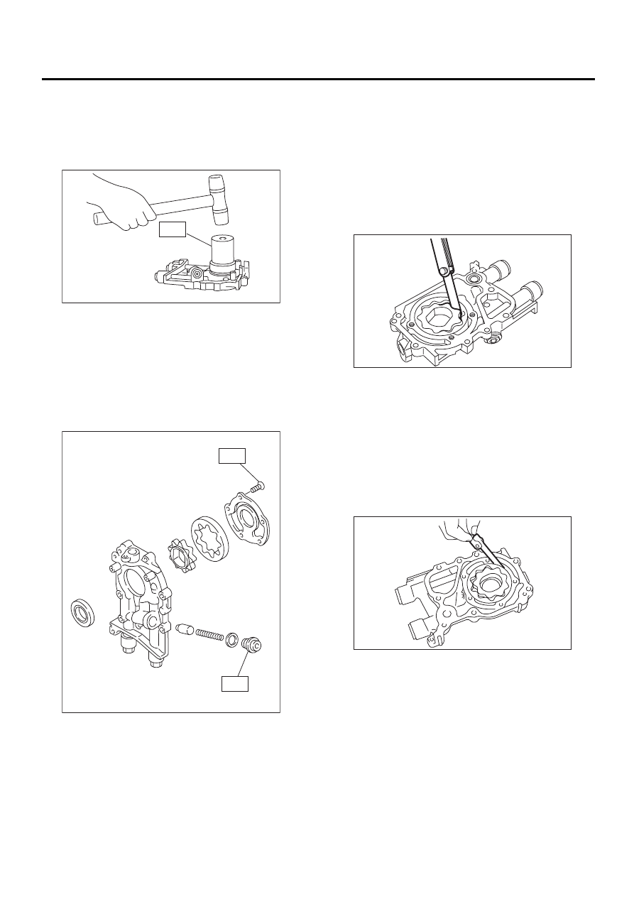
D: ASSEMBLY
1) Install front oil seal by using ST.
ST
499587100
OIL SEAL INSTALLER
NOTE:
Use a new oil seal.
2) Apply engine oil to inner and outer rotors.
3) Install inner and outer rotors in their original po-
sitions.
4) Install oil relief valve and relief valve spring.
5) Install oil pump cover.
Tightening torque:
T1: 5 N·m (0.5 kgf-m, 3.6 ft-lb)
T2: 44 N·m (4.5 kgf-m, 33 ft-lb)
E: INSPECTION
1. TIP CLEARANCE
Measure the tip clearance of rotors. If the clearance
exceeds the limit, replace rotors as a set.
Tip clearance:
Standard
0.04 — 0.14 mm (0.0016 — 0.0055 in)
Limit
0.18 mm (0.0071 in)
2. CASE CLEARANCE
Measure the clearance between the outer rotor and
the cylinder block rotor housing. If the clearance
exceeds the limit, replace the rotor.
Case clearance:
Standard
0.10 — 0.175 mm (0.0039 — 0.0069 in)
Limit
0.20 mm (0.0079 in)
LU-00021
ST
T1
T2
LU-00022
LU-00023
LU-00024
LU(H4SO)-13
LUBRICATION
OIL PUMP
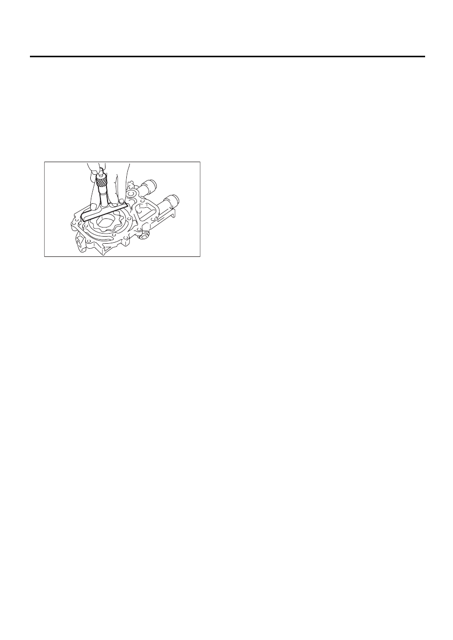
3. SIDE CLEARANCE
Measure clearance between oil pump inner rotor
and pump cover. If the clearance exceeds the limit,
replace rotor or pump body.
Side clearance:
Standard
0.02 — 0.07 mm (0.0008 — 0.0028 in)
Limit
0.12 mm (0.0047 in)
4. OIL RELIEF VALVE
Check the valve for fitting condition and damage,
and the relief valve spring for damage and deterio-
ration. Replace the parts if defective.
Relief valve spring:
Free length
72.8 mm (2.866 in)
Installed length
54.7 mm (2.154 in)
Load when installed
81.3 N (8.29 kgf, 18.28 lb)
5. OIL PUMP CASE
Check the oil pump case for worn shaft hole,
clogged oil passage, worn rotor chamber, cracks,
and other faults.
6. OIL SEAL
Check the oil seal lips for deformation, hardening,
wear, etc. and replace if defective.
LU-00025
Нет комментариевНе стесняйтесь поделиться с нами вашим ценным мнением.
Текст