Subaru Legacy III (2000-2003 year). Service manual — part 693
ABS-12
ABS
FRONT ABS SENSOR
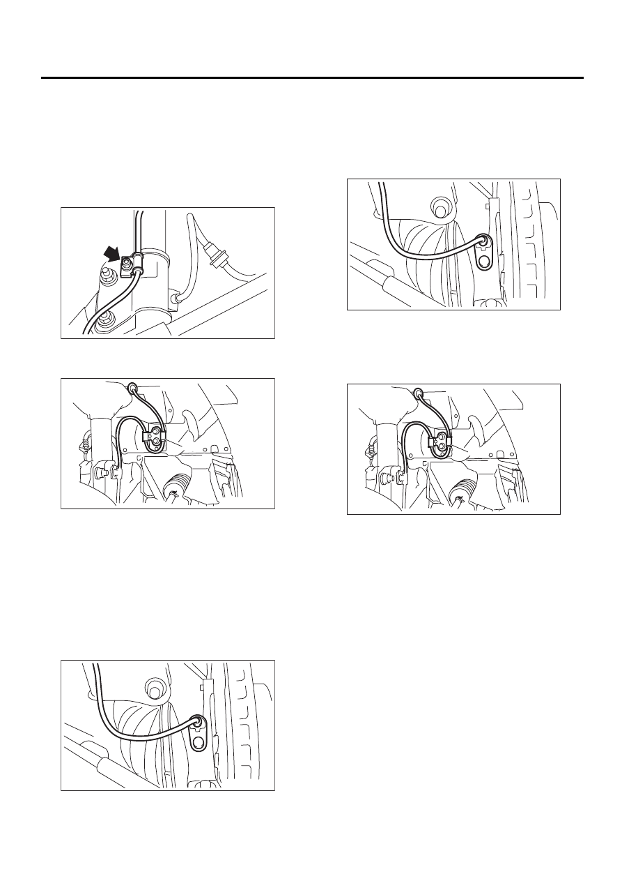
4. Front ABS Sensor
A: REMOVAL
1) Disconnect battery ground cable.
2) Disconnect front ABS sensor connector located
next to front strut mounting house in engine com-
partment.
3) Remove bolts which secure sensor harness to
strut.
4) Remove bolts which secure sensor harness to
body.
5) Remove bolts which secure front ABS sensor to
housing, and remove front ABS sensor.
CAUTION:
• Be careful not to damage pole piece located
at tip of the sensor and teeth faces during re-
moval.
• Do not pull sensor harness during removal.
B: INSTALLATION
1) Temporarily install front ABS sensor on housing.
CAUTION:
Be careful not to strike ABS sensor's pole piece
and tone wheel's teeth against adjacent metal
parts during installation.
2) Install front ABS sensor on strut and wheel
apron bracket.
Tightening torque:
33 N·m (3.3 kgf-m, 24 ft-lb)
(1) To front ABS sensor connector
(2) Bracket
ABS00140
( 1 )
( 2 )
ABS00141
ABS00142
(1) To front ABS sensor connector
(2) Bracket
ABS00142
( 1 )
( 2 )
ABS00141
ABS-13
ABS
FRONT ABS SENSOR
3) Place a thickness gauge between ABS sensor's
pole piece and tone wheel's tooth face. After stan-
dard clearance is obtained over the entire perime-
ter, tighten ABS sensor on housing to specified
torque.
ABS sensor standard clearance:
0.3 — 0.8 mm (0.012 — 0.031 in)
Tightening torque:
33 N·m (3.3 kgf-m, 24 ft-lb)
CAUTION:
Check the marks on the harness to make sure
that no distortion exists.
NOTE:
If the clearance is outside specifications, adjust the
gap using spacer (Part No. 26755AA000).
4) After confirmation of the ABS sensor clearance,
connect connector to ABS sensor.
5) Connect connector to battery ground cable.
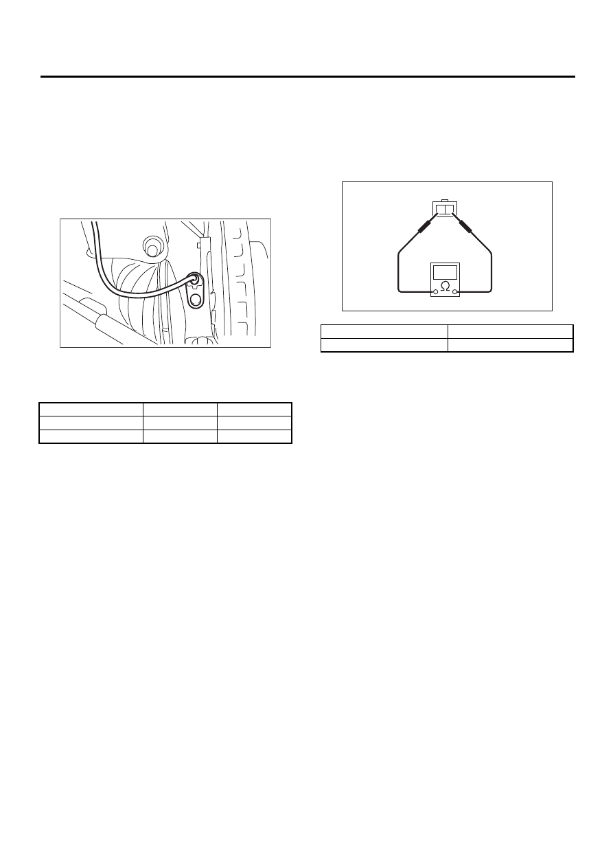
C: INSPECTION
1. ABS SENSOR
1) Check pole piece of ABS sensor for foreign par-
ticles or damage. If necessary, clean pole piece or
replace ABS sensor.
2) Measure ABS sensor resistance.
CAUTION:
If resistance is outside the standard value, re-
place ABS sensor with new one.
NOTE:
Check ABS sensor cable for discontinuity. If neces-
sary, replace with a new one.
Model
LH
RH
Except OUTBACK
Yellow
White
OUTBACK
Brown
Light blue
ABS00142
Terminal No.
Standard
1 and 2
1.25
±
0.25 k
Ω
ABS00143
2 1
ABS-14
ABS
FRONT ABS SENSOR
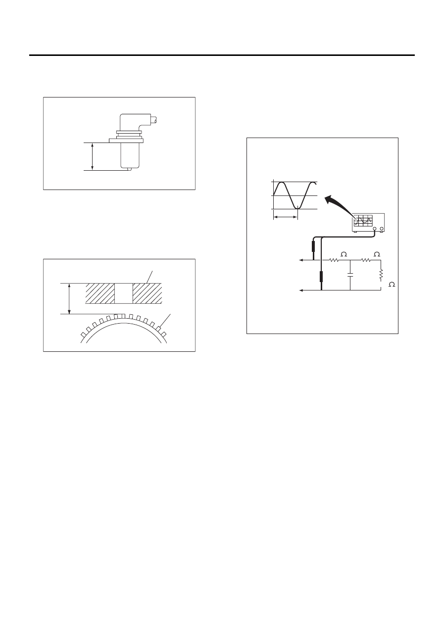
2. SENSOR GAP
1) Measure the distance “A” between ABS sensor
surface and sensor pole face.
2) Measure the distance “B” between surface
where the front axle housing meets the ABS sen-
sor, and the tone wheel.
NOTE:
Measure so that the gauge touches the tone wheel
teeth top.
3) Find the gap between the ABS sensor pole face
and the surface of the tone wheel teeth by putting
the measured valves in the formula below and cal-
culating.
ABS sensor clearance = B
−−−−
A
ABS sensor standard clearance:
0.3 — 0.8 mm (0.012 — 0.031 in)
NOTE:
If the clearance is outside specifications, adjust the
gap using spacer (Part No. 26755AA000).
3. OUTPUT VOLTAGE
Output voltage can be checked by the following
method. Install resistor and condenser, then rotate
wheel about 2.75 km/h (2 MPH) or equivalent.
NOTE:
Regarding terminal No., please refer to item 1. ABS
SENSOR.
D: ADJUSTMENT
Adjust the gap using spacer (Part No.
26755AA000).
(1) Axle housing
(2) Tone wheel
ABS00161
A
ABS00145
B
( 1 )
( 2 )
(1) Standard output voltage:
Approx. 120 mV (When it is 10 Hz)
(2) To terminal
(3) Oscilloscope
ABS00162
10 Hz
3.9 k
14.7 k
10 nF
+60 mV
0
–60 mV
100 k
( 1 )
( 2 )
( 2 )
( 3 )
ABS-15
ABS
REAR ABS SENSOR
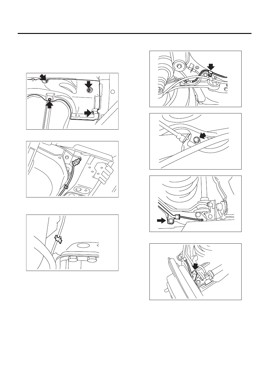
5. Rear ABS Sensor
A: REMOVAL
1) Disconnect battery ground cable.
2) Lift-up the vehicle.
3) Remove fuel tank cover.
4) Disconnect rear ABS sensor connector.
5) Remove rear sensor harness from clip on body
side.
6) Remove bolts which hold rear sensor harness
brackets.
7) Remove rear ABS sensor from rear arm.
ABS00163
ABS00164
ABS00165
ABS00166
ABS00167
ABS00168
ABS00169
Нет комментариевНе стесняйтесь поделиться с нами вашим ценным мнением.
Текст