Subaru Legacy III (2000-2003 year). Service manual — part 691
ABS-4
ABS
GENERAL DESCRIPTION
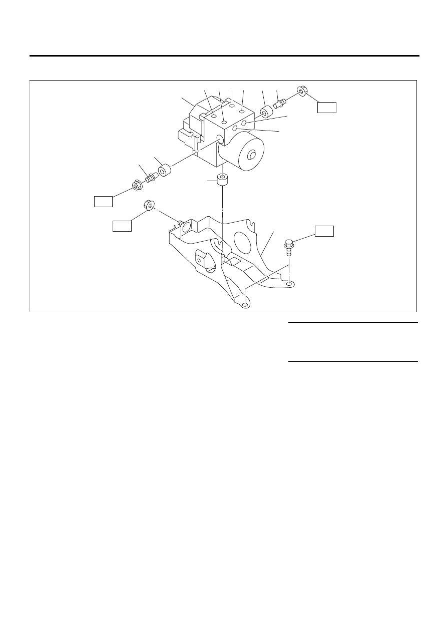
2. ABS CONTROL MODULE AND HYDRAULIC CONTROL UNIT (ABSCM&H/U)
(1) Stud bolt
(6) Front-RH outlet
Tightening torque: N·m (kgf-m, ft-lb)
(2) Damper
(7) Primary inlet
T1: 18 (1.8, 13.06)
(3) ABS control module and hydrau-
lic control unit
(8) Rear-LH outlet
T2: 33 (3.3, 24)
(9) Rear-RH outlet
T3: 38 (3.8, 27)
(4) Front-LH outlet
(10) Bracket
(5) Secondary inlet
ABS00130
( 9 )
( 8 )
( 7 )
( 6 )
( 5 )
( 4 )
( 3 )
( 2 )
( 2 )
( 2 )
( 1 )
( 1 )
(10)
T2
T3
T1
T1
ABS-5
ABS
GENERAL DESCRIPTION
C: CAUTION
• Wear working clothing, including a cap, protec-
tive goggles, and protective shoes during opera-
tion.
• Remove contamination including dirt and corro-
sion before removal, installation or disassembly.
• Keep the disassembled parts in order and pro-
tect them from dust or dirt.
• Before removal, installation or disassembly, be
sure to clarify the failure. Avoid unnecessary re-
moval, installation, disassembly, and replacement.
• Be careful not to burn your hands, because each
part in the vehicle is hot after running.
• Be sure to tighten fasteners including bolts and
nuts to the specified torque.
• Place shop jacks or safety stands at the specified
points.
• Before disconnecting electrical connectors of
sensors or units, be sure to disconnect ground ca-
ble from battery.
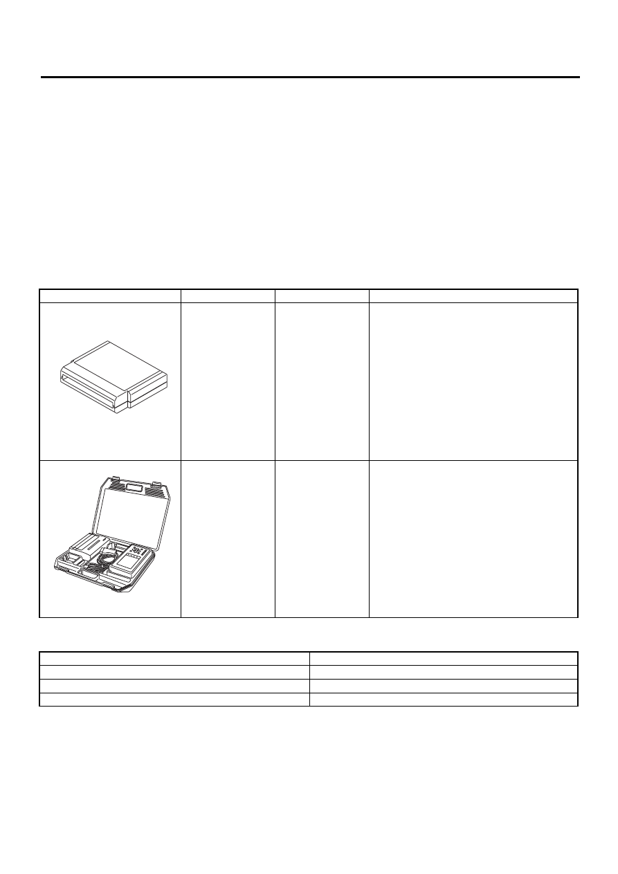
D: PREPARATION TOOL
1. SPECIAL TOOLS
2. GENERAL PURPOSE TOOLS
ILLUSTRATION
TOOL NUMBER
DESCRIPTION
REMARKS
24082AA210
CARTRIDGE
Troubleshooting for electrical systems.
22771AA030
SELECT MONITOR
KIT
Troubleshooting for electrical systems.
• English: 22771AA030 (Without printer)
• German: 22771AA070 (Without printer)
• French: 22771AA080 (Without printer)
• Spanish: 22771AA090 (Without printer)
TOOL NAME
REMARKS
Circuit Tester
Used for measuring resistance, voltage and ampere.
Pressure Gauge
Used for measuring oil pressure.
Oscilloscope
Used for measuring sensor.
ST24082AA210
ST22771AA030
ABS-6
ABS
ABS CONTROL MODULE AND HYDRAULIC CONTROL UNIT (ABSCM&H/U)
2. ABS Control Module and Hy-
draulic Control Unit (AB-
SCM&H/U)
A: REMOVAL
1) Disconnect ground cable from battery.
2) Remove air intake duct from engine compart-
ment to facilitate removal of ABSCM&H/U.
3) Use an air gun to get rid of water around the AB-
SCM&H/U.
CAUTION:
The contact will be insufficient if the terminal
gets wet.
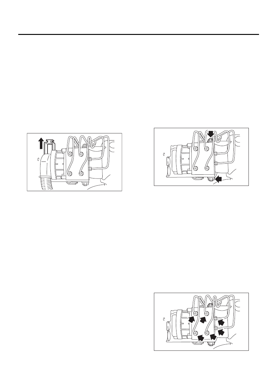
4) Pull off the lock of the ABSCM&H/U connector to
remove it.
5) Disconnect connector from ABSCM&H/U.
CAUTION:
Be careful not to let water or other foreign mat-
ter contact the ABSCM&H/U terminal.
6) Unlock cable clip.
7) Disconnect brake pipes from ABSCM&H/U.
CAUTION:
Wrap brake pipes with vinyl bag to avoid spill-
ing brake fluid on vehicle body.
8) Remove ABSCM&H/U ground terminal from
bracket.
9) Remove ABSCM&H/U from engine compart-
ment.
CAUTION:
• ABSCM&H/U cannot be disassembled. Do
not attempt to loosen bolts and nuts.
• Do not drop or bump ABSCM&H/U.
• Do not turn the ABSCM&H/U upside down or
place it on its side.
• Be careful to prevent foreign particles from
getting into ABSCM&H/U.
• Apply a coat of rust-preventive wax (Nippeco
LT or GB) to bracket attaching bolt after tight-
ening.
• Do not pull harness when disconnecting con-
nector.
B: INSTALLATION
1) Install ABSCM&H/U.
CAUTION:
Confirm that the specifications of the AB-
SCM&H/U conforms to the vehicle specifica-
tions.
Tightening torque:
18 N·m (1.8 kgf-m, 13.0 ft-lb)
2) Install ABSCM&H/U ground terminal to bracket.
Tightening torque:
33 N·m (3.3 kgf-m, 24 ft-lb)
3) Connect brake pipes to their correct ABSCM&H/
U connections.
Tightening torque:
15 N·m (1.5 kgf-m, 10.8 ft-lb)
ABS00131
ABS00132
ABS00314
ABS-7
ABS
ABS CONTROL MODULE AND HYDRAULIC CONTROL UNIT (ABSCM&H/U)
4) Using cable clip, secure ABSCM&H/U harness
to bracket.
5) Connect connector to ABSCM&H/U.
CAUTION:
• Be sure to remove all foreign matter from in-
side the connector before connecting.
• Ensure that the ABSCM&H/U connector is se-
curely locked.
6) Install air intake duct.
7) Connect ground cable to battery.
8) Bleed air from the brake system.
C: INSPECTION
1) Check connected and fixed condition of connec-
tor.
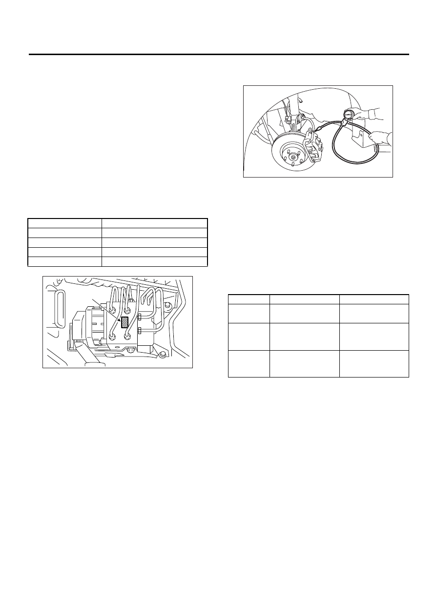
2) Check specifications of the mark with AB-
SCM&H/U.
1. CHECKING THE HYDRAULIC UNIT ABS
OPERATION BY PRESSURE GAUGE
1) Lift-up vehicle and remove wheels.
2) Disconnect the air bleeder screws from the FL
and FR caliper bodies.
3) Connect two pressure gauges to the FL and FR
caliper bodies.
CAUTION:
• Pressure gauges used exclusively for brake
fluid must be used.
• Do not employ pressure gauge previously
used for transmission since the piston seal is
expanded which may lead to malfunction of the
brake.
NOTE:
Wrap sealing tape around the pressure gauge.
4) Bleed air from the pressure gauges.
5) Perform ABS sequence control.
<Ref. to ABS-9, ABS Sequence Control.>
6) When the hydraulic unit begins to work, and first
the FL side performs decompression, holding, and
compression, and then the FR side performs de-
compression, holding, and compression.
7) Read values indicated on the pressure gauge
and check if the fluctuation of the values between
decompression and compression meets the stan-
dard values. Also check if any irregular brake pedal
tightness is felt.
8) Remove pressure gauges from FL and FR cali-
per bodies.
9) Remove air bleeder screws from the RL and RR
caliper bodies.
10) Connect the air bleeder screws to the FL and
FR caliper bodies.
11) Connect two pressure gauges to the RL and
RR caliper bodies.
12) Bleed air from the pressure gauges and the FL
and FR caliper bodies.
13) Perform ABS sequence control.
<Ref. to ABS-9, ABS Sequence Control.>
14) When the hydraulic unit begins to work, at first
the RR side performs decompression, holding, and
compression, and then the RL side performs de-
compression, holding, and compression.
15) Read values indicated on the pressure gauges
and check if they meet the standard value.
16) After checking, remove the pressure gauges
from caliper bodies.
Mark
Model
CG
AT (Except OUTBACK)
CH
MT (Except OUTBACK)
CI
AT (OUTBACK)
CJ
MT (OUTBACK)
(1) Mark
ABS00133
(1)
Front wheel
Rear wheel
Initial value
3,432 kPa
(35 kg/cm
2
, 498 psi)
3,432 kPa
(35 kg/cm
2
, 498 psi)
When
decom-
pressed
490 kPa
(5 kg/cm
2
, 71 psi)
or less
490 kPa
(5 kg/cm
2
, 71 psi)
or less
When
com-
pressed
3,432 kPa
(35 kg/cm
2
, 498 psi)
or more
3,432 kPa
(35 kg/cm
2
, 498 psi)
or more
ABS00134
Нет комментариевНе стесняйтесь поделиться с нами вашим ценным мнением.
Текст