Subaru Legacy III (2000-2003 year). Service manual — part 281
CO(H6DO)-22
COOLING
ENGINE COOLANT
4. Engine Coolant
A: REPLACEMENT
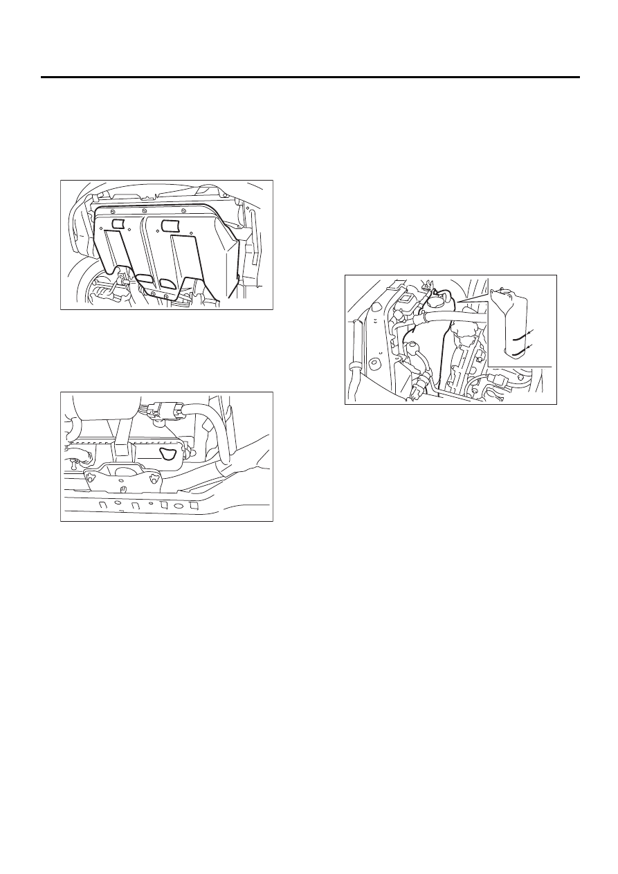
1. DRAINING OF ENGINE COOLANT
1) Lift-up the vehicle.
2) Remove under cover.
3) Remove drain cock to drain engine coolant into
container.
NOTE:
Remove radiator cap so that engine coolant will
drain faster.
2. FILLING OF ENGINE COOLANT
1) Fill engine coolant into radiator up to filler neck
position.
Coolant amount for refill:
Approx. 7.9
2
(8.4 US qt, 7.0 Imp qt)
CAUTION:
The SUBARU Genuine Coolant containing anti-
freeze and anti-rust agents is especially made
for SUBARU engine, which has an aluminum
crankcase. Always use SUBARU Genuine Cool-
ant, since other coolant may cause corrosion.
2) Fill engine coolant into reservoir tank up to upper
level.
3) Attach radiator cap and reservoir tank cap prop-
erly.
4) Warm-up engine completely for more than five
minutes at 2,000 to 3,000 rpm.
5) If engine coolant level drops in radiator, add en-
gine coolant to filler neck position.
6) If engine coolant level drops from upper level of
reservoir tank, add engine coolant to upper level.
7) Attach radiator cap and reservoir tank cap prop-
erly.
EX-00057
CO-00109
(1) Full level
(2) Low level
CO-00110
( 1 )
( 2 )
CO(H6DO)-23
COOLING
ENGINE COOLANT
B: INSPECTION
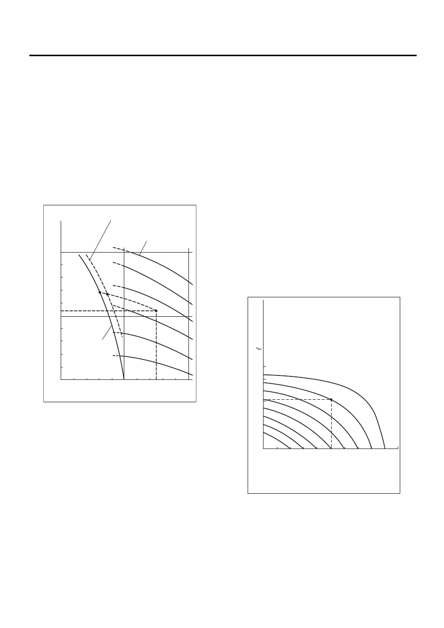
1. RELATIONSHIP OF SUBARU COOLANT
CONCENTRATION AND FREEZING TEM-
PERATURE
The concentration and safe operating temperature
of the SUBARU coolant is shown in the diagram.
Measuring the temperature and specific gravity of
the coolant will provide this information.
[Example]
If the coolant temperature is 25
°
C (77
°
F) and its
specific gravity is 1.054, the concentration is 35%
(point A), the safe operating temperature is
−
14
°
C
(7
°
F) (point B), and the freezing temperature is
−
20
°
C (
−
4
°
F) (point C).
2. PROCEDURE TO ADJUST THE CON-
CENTRATION OF THE COOLANT
To adjust the concentration of the coolant accord-
ing to temperature, find the proper fluid concentra-
tion in the above diagram and replace the
necessary amount of coolant with an undiluted so-
lution of SUBARU genuine coolant (concentration
50).
The amount of coolant that should be replaced can
be determined using the diagram.
[Example]
Assume that the coolant concentration must be in-
creased form 25% to 40%. Find point A, where the
25% line of coolant concentration intersects with
the 40% curve of the necessary coolant concentra-
tion, and read the scale on the vertical axis of the
graph at height A. The quantity of coolant to be
drained is 2.1 liters (2.2 US qt, 1.8 Imp qt). Drain
2.1 liters (2.2 US qt, 1.8 Imp qt) of coolant from the
cooling system and add 2.1 liters (2.2 US qt, 1.8
Imp qt) of the undiluted solution of SUBARU cool-
ant.
If a coolant concentration of 50% is needed, drain
all the coolant and refill with the undiluted solution
only.
CO-00111
1.000
1.010
–40
(–40)
1.020
1.030
1.040
1.050
1.060
(1.054)
1.070
C
B
A
1.080
1.090
1.100
–30
(–22)
–20
(–4)
–10
(14)
0
(32)
10
10%
20%
30%
40%
50%
60%
(50)
20
25
˚C
(77
˚F)
(68)
30
(86)
40
(104)
50
(122)
Specific gravity
of coolant
Safe operating temperature
Concentration
of coolant
Freezing
temperature
Coolant temperature ˚C (˚F)
CO-00112
10
0
1
(1.1,
0.9)
(2.1,
1.8)
(3.2,
2.6)
2
45%
40%
35%
30%
25%
20%
15%
10%
20
30
40
50
3
A
Quantity of coolant to be
drained (US qt, lmp qt)
Necessary concentration
of coolant
Concentration of coolant in
the vehicle cooling system %
Concentration of coolant in vehicle
and quantity to be drained
CO(H6DO)-24
COOLING
WATER PUMP
5. Water Pump
A: REMOVAL
1) Remove radiator. <Ref. to CO(H6DO)-27, RE-
MOVAL, Radiator.>
2) Remove V-belt.
<Ref. to ME(H6DO)-28, REMOVAL, V-belt.>
3) Remove front chain cover.
<Ref. to ME(H6DO)-39, REMOVAL, Front Chain
Cover.>
4) Remove timing chain.
<Ref. to ME(H6DO)-41, REMOVAL, Timing Chain
Assembly.>
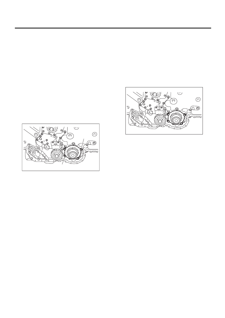
5) Remove water pump.
NOTE:
When water pump cannot be easily removed, in-
stall M8 bolt in opposing bolt holes (“A” in figure).
Alternately tightening each bolt should be enough
to gradually free water pump from rear chain cover.
B: INSTALLATION
1) Install water pump onto rear chain cover.
NOTE:
Apply engine coolant to O-ring.
Tightening torque:
6.4 N·m (0.65 kgf-m, 4.7 ft-lb)
NOTE:
• Replace O-rings with a new one.
• Applying engine coolant to O-ring makes water
pump installation easier.
2) Install timing chain assembly. <Ref. to
ME(H6DO)-42, INSTALLATION, Timing Chain As-
sembly.>
3) Install front chain cover.
<Ref. to ME(H6DO)-39, INSTALLATION, Front
Chain Cover.>
4) Install V-belt. <Ref. to ME(H6DO)-28, INSTAL-
LATION, V-belt.>
5) Install radiator. <Ref. to CO(H6DO)-28, INSTAL-
LATION, Radiator.>
6) Fill coolant. <Ref. to CO(H6DO)-22, FILLING OF
ENGINE COOLANT, REPLACEMENT, Engine
Coolant.>
C: INSPECTION
1) Check water pump bearing for smooth rotation.
2) Check water pump sprocket for abnormalities.
CO-00113
( A )
( A )
CO-00114
CO(H6DO)-25
COOLING
THERMOSTAT
6. Thermostat
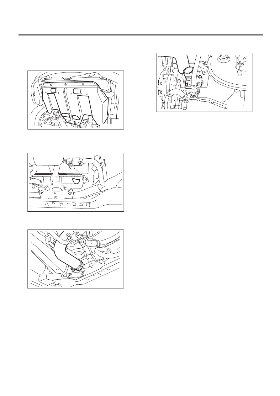
A: REMOVAL
1) Lift-up the vehicle.
2) Remove under cover.
3) Drain engine coolant completely. <Ref. to
CO(H6DO)-22, DRAINING OF ENGINE COOL-
ANT, REPLACEMENT, Engine Coolant.>
4) Disconnect radiator outlet hose from thermostat
cover.
5) Remove thermostat cover and gasket, and pull
out the thermostat.
B: INSTALLATION
1) Install the thermostat to oil pan upper, and install
the thermostat cover together with a gasket.
NOTE:
When reinstalling the thermostat, use a new gas-
ket.
Tightening torque:
6.4 N·m (0.65 kgf-m, 4.7 ft-lb)
2) Connect radiator outlet hose to thermostat cov-
er.
3) Fill coolant. <Ref. to CO(H6DO)-22, FILLING OF
ENGINE COOLANT, REPLACEMENT, Engine
Coolant.>
EX-00057
CO-00109
CO-00115
CO-00116
Нет комментариевНе стесняйтесь поделиться с нами вашим ценным мнением.
Текст