Subaru Legacy III (2000-2003 year). Service manual — part 279
CO(H6DO)-14
COOLING
RADIATOR SUB FAN SYSTEM
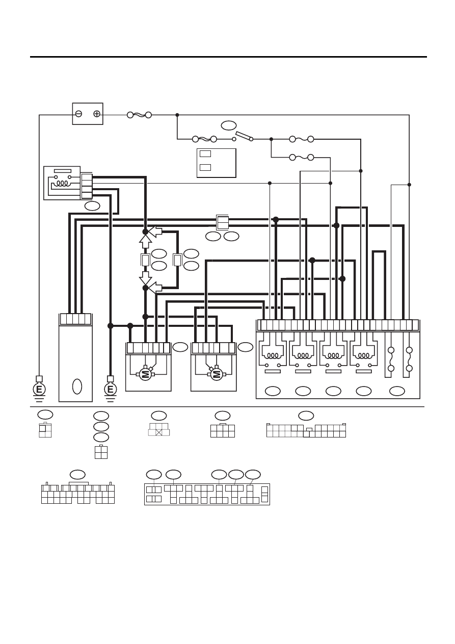
3. Radiator Sub Fan System
A: SCHEMATIC
CO-00167
2
1
4
3
28
27
25
29
8
7
5
9
31
32
34
30
21
22
24
20
30A
30A
SUB FAN
RELAY-1
AIR CONDITIONING RELAY HOLDER
SUB FAN
MOTOR
MAIN FAN
MOTOR
MAIN FAN
RELAY-1
F28
F16
F66
SUB FAN
RELAY-2
MAIN FAN
RELAY-2
F29
F30
F27
F17
B100
F2
B72
NO. 18
NO. 17
SBF-4
SBF-1
IGNITION
SWITCH
RELAY HOLDER (BLACK)
B72
F16
B253
F17
F46
3 4
1 2
B137
BATTERY
17
24
28
B137
ENG
INE C
O
NTR
O
L
M
O
DU
LE
B253
FAN RELAY
5
1
3
4
3
3
4
4
1
1
2
2
1
2
7
8
9
5
6
3
4
10 11 12
19 20 21
29 30 31
13 14 15 16 17
27 28
18
22 23 24 25 26
3 4
1 2
1
3
4
5
2
1
F46
B108
1
F44
B61
LHD
LHD
RHD
RHD
1
*
2
*
1
*
2
*
LHD : 7
LHD : 6
RHD : 5
RHD : 6
1 2 3 4
5 6 7 8
F44
F2
3 4
1 2
8 9 10 11
12 13 14 15 16 17 18 19 20 21 22 23 24
5 6
7
1
2
5 6
8
9
7
3
4
25 26 27
28
29
30
31
32 33 34
10
11
12 13 14
15 16 17
18
19
20
21
22 23 24
35
36
F30
F28
F29
F66
F27
CO(H6DO)-15
COOLING
RADIATOR SUB FAN SYSTEM
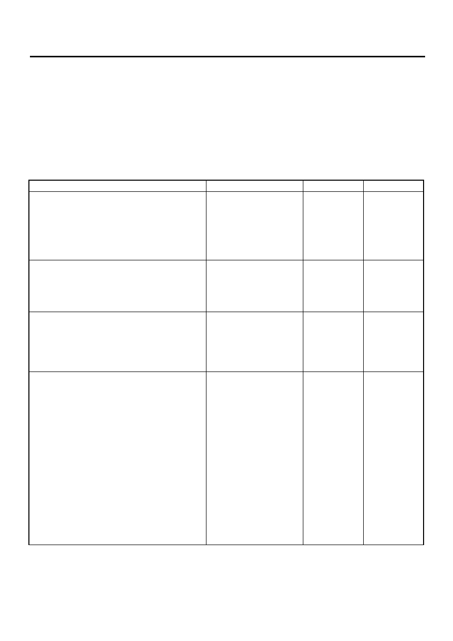
B: INSPECTION
TROUBLE SYMPTOM:
• Radiator sub fan does not rotate in low speed under the following conditions:
(1) Coolant temperature 98 — 101
°
C (208 — 214
°
F).
(2) A/C switch set to OFF.
• Radiator sub fan does not rotate in middle speed under the following conditions:
(1) Coolant temperature 97
°
C (207
°
F) or less.
(2) A/C switch set to ON and A/C temperature at the lowest position.
• Radiator sub fan does not rotate in high speed under the following conditions:
(1) Coolant temperature 98 — 101
°
C (208 — 214
°
F).
(2) A/C switch set to ON and A/C temperature at the lowest position.
Step
Value
Yes
No
1
CHECK OPERATION OF RADIATOR FAN.
1) Run the engine at idle (Vehicle stationary)
2) Turn the A/C switch to ON, set temperature
at the lowest position.
3) Inspect while coolant temperature is 97
°
C
(207
°
F) or less.
When A/C compressor is operating, does
the radiator sub fan rotate in middle speed?
Rotates in middle speed.
2
CHECK OPERATION OF RADIATOR FAN.
1) Turn the A/C switch to OFF.
2) Perform checking procedure during coolant
temperature is 98 — 101
°
C (208 — 214
°
F).
When A/C compressor is operating, does
the radiator sub fan rotate in low speed?
Rotates in low speed.
3
CHECK OPERATION OF RADIATOR FAN.
1) Turn the A/C switch to ON, set temperature
at the lowest position.
2) Perform checking procedure during coolant
temperature is 98 — 101
°
C (208 — 214
°
F).
When A/C compressor is operating, does
the radiator sub fan rotate in high speed?
Rotates in high speed.
Radiator sub fan
system is okay.
4
CHECK POWER SUPPLY TO SUB FAN MO-
TOR.
CAUTION:
Be careful not to overheat engine during re-
pair.
1) Turn ignition switch to OFF.
2) Disconnect connector from sub fan motor.
3) Start the engine, keep coolant temperature
below 97
°
C (207
°
F).
4) Turn the A/C switch to ON, set temperature
at the lowest position.
5) Measure voltage while A/C compressor is
rotating.
6) Measure voltage between sub fan motor
connector and chassis ground.
Connector & terminal
(F16) No. 1 (+) — Chassis ground (
−−−−
):
(F16) No. 2 (+) — Chassis ground (
−−−−
):
Does the measured value exceed the spec-
ified value?
10 V
CO(H6DO)-16
COOLING
RADIATOR SUB FAN SYSTEM
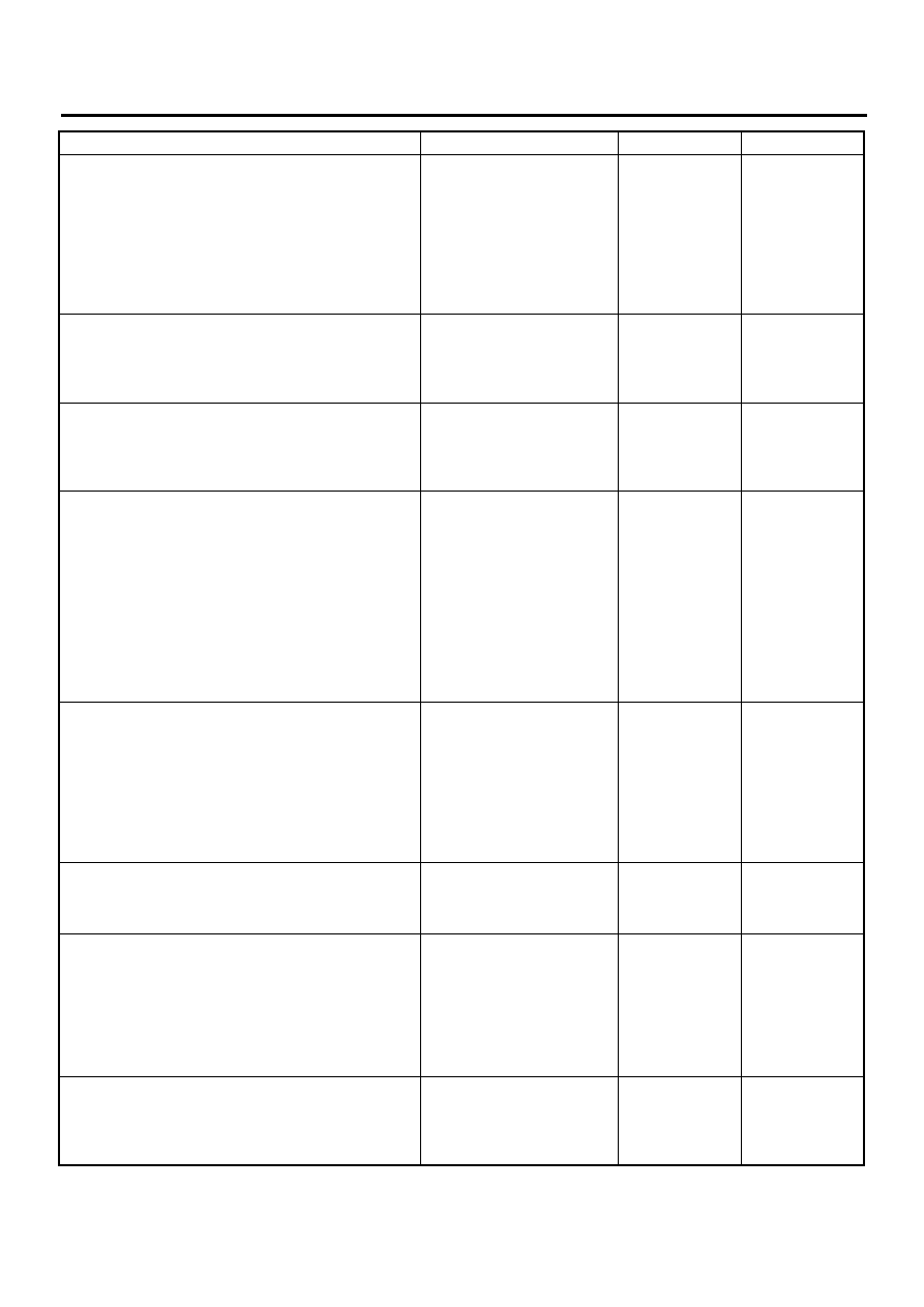
5
CHECK GROUND CIRCUIT OF SUB FAN
MOTOR.
1) Turn ignition switch to OFF.
2) Measure resistance between sub fan motor
connector and chassis ground.
Connector & terminal
(F16) No. 4 — Chassis ground:
Is the measured value less than the speci-
fied value?
5
Ω
Repair open circuit
in harness
between sub fan
motor connector
and chassis
ground.
6
CHECK POOR CONTACT.
Check poor contact in sub fan motor connec-
tor.
Is there poor contact in sub fan motor connec-
tor?
There is poor contact.
Repair poor con-
tact in sub fan
motor connector.
7
CHECK SUB FAN MOTOR.
Connect battery positive (+) terminal to termi-
nals No. 1 and No. 2 and negative (
−
) terminal
to terminal No. 4 of sub fan motor connector.
Does the sub fan rotate?
Rotates.
Repair poor con-
tact in sub fan
motor connector.
Replace sub fan
motor with a new
one.
8
CHECK POWER SUPPLY TO SUB FAN RE-
LAYS 1 AND 2.
1) Remove sub fan relays 1 and 2 from A/C
relay holder.
2) Turn ignition switch to ON.
3) Measure voltage between sub fan relays 1
and 2 terminal and chassis ground.
Connector & terminal
(F28) No. 28 (+) — Chassis ground (
−−−−
):
(F29) No. 31 (+) — Chassis ground (
−−−−
):
Does the measured value exceed the spec-
ified value?
10 V
9
CHECK POWER SUPPLY TO SUB FAN RE-
LAYS 1 AND 2.
Measure voltage between sub fan relays 1 and
2 terminal and chassis ground.
Connector & terminal
(F28) No. 25 (+) — Chassis ground (
−−−−
):
(F29) No. 34 (+) — Chassis ground (
−−−−
):
Does the measured value exceed the specified
value?
10 V
10
CHECK 30 A FUSE.
1) Remove 30 A fuse from A/C relay holder.
2) Check condition of fuse.
Is the fuse blown-out?
Fuse is blown-out.
Replace fuse.
11
CHECK POWER SUPPLY TO A/C RELAY
HOLDER 30 A FUSE TERMINAL.
Measure voltage of harness between A/C relay
holder 30 A fuse terminal and chassis ground.
Connector & terminal
(F27) No. 3 (+) — Chassis ground (
−−−−
):
Does the measured value exceed the specified
value?
10 V
Repair open circuit
in harness
between 30 A fuse
and sub fan relays
1 and 2 terminal.
Repair open circuit
in harness
between main fuse
box connector and
30 A fuse terminal.
12
CHECK FUSE.
1) Turn ignition switch to OFF.
2) Remove fuse No. 17 from joint box.
3) Check condition of fuse.
Is the fuse blown-out?
Fuse is blown-out.
Replace fuse.
Repair open circuit
in harness
between sub fan
relays 1 and 2 and
ignition switch.
Step
Value
Yes
No
CO(H6DO)-17
COOLING
RADIATOR SUB FAN SYSTEM
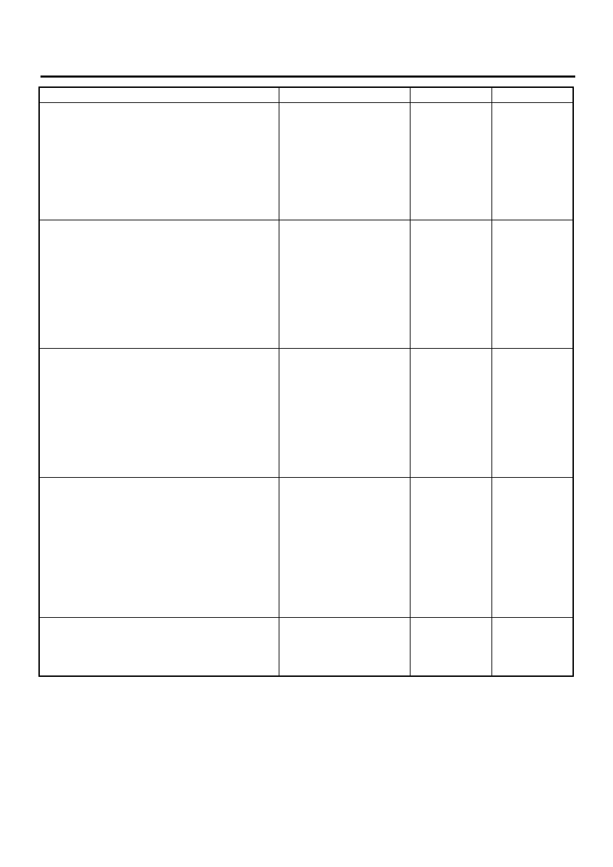
13
CHECK SUB FAN RELAYS 1 AND 2.
1) Turn ignition switch to OFF.
2) Remove sub fan relays 1 and 2.
3) Measure resistance of sub fan relays 1 and
2.
Terminal
No. 28 — No. 29:
No. 30 — No. 31:
Does the measured value exceed the spec-
ified value?
1 M
Ω
Replace sub fan
relays 1 and 2.
14
CHECK SUB FAN RELAYS 1 AND 2.
1) Connect battery to terminals No. 25 and
No. 27 of sub fan relay 1 or to terminals No.
32 and No. 34 of sub fan relay 2.
2) Measure resistance of sub fan relays 1 and
2.
Terminal
No. 28 — No. 29:
No. 30 — No. 31:
Is the measured value less than the speci-
fied value?
1
Ω
Replace sub fan
relays 1 and 2.
15
CHECK HARNESS BETWEEN SUB FAN RE-
LAYS 1 AND 2 TERMINAL AND SUB FAN
MOTOR CONNECTOR.
Measure resistance of harness between sub
fan motor connector and sub fan relays 1 and
2 terminal.
Connector & terminal
(F16) No. 1 — (F28) No. 29:
(F16) No. 2 — (F29) No. 30:
Is the measured value less than the specified
value?
1
Ω
Repair open circuit
in harness
between sub fan
motor connector
and sub fan relays
1 and 2 terminal.
16
CHECK HARNESS BETWEEN SUB FAN RE-
LAYS 1 AND 2 AND ECM.
1) Turn ignition switch to OFF.
2) Disconnect connector from ECM.
3) Measure resistance of harness between
sub fan relays 1 and 2 connector and ECM
connector.
Connector & terminal
(F28) No. 27 — (B137) No. 28:
(F29) No. 32 — (B137) No. 17:
Is the measured value less than the speci-
fied value?
1
Ω
Repair open circuit
in harness
between sub fan
relays 1 and 2 and
ECM.
17
CHECK POOR CONTACT.
Check poor contact in connector between sub
fan and ECM.
Is there poor contact in connector between sub
fan motor and ECM.
There is poor contact.
Repair poor con-
tact connector.
Contact SUBARU
distributor service.
Step
Value
Yes
No
Нет комментариевНе стесняйтесь поделиться с нами вашим ценным мнением.
Текст