Subaru Legacy III (2000-2003 year). Service manual — part 619
MT-44
MANUAL TRANSMISSION AND DIFFERENTIAL
SWITCHES AND HARNESS
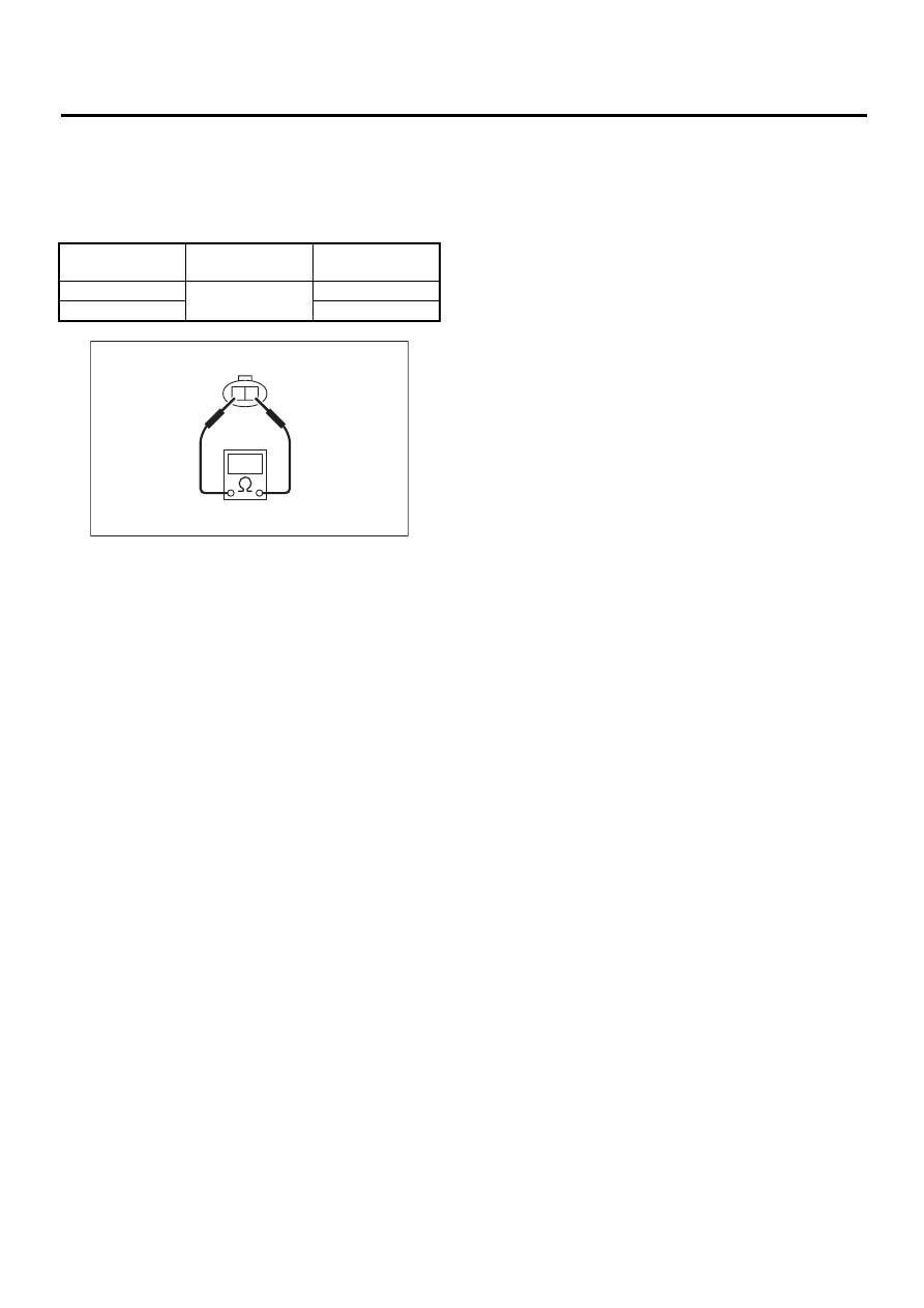
3. HIGH-LOW SWITCH
1) Turn ignition switch to OFF.
2) Disconnect connector high-low switch.
3) Measure resistance between HIGH-LOW switch
terminals.
4) Replace defective parts if outside the standard
value.
Gear shift position
Terminal No.
Specified resis-
tance
Lo position
1 and 2
Less than 1
Ω
Hi position
More than 1 M
Ω
MT-00112
1
2
MT-45
MANUAL TRANSMISSION AND DIFFERENTIAL
VEHICLE SPEED SENSOR
7. Vehicle Speed Sensor
A: REMOVAL
1) Disconnect battery ground cable.
2) Lift-up the vehicle.
3) Remove front, center exhaust pipes. (Non-TUR-
BO model)
Without OBD
<Ref. to EX(H4SOw/oOBD)-9, REMOVAL, Front
Exhaust Pipe.>
With OBD
<Ref. to EX-<Ref. to EX(H4SO)-5, REMOVAL,
Front Exhaust Pipe.>
4) Remove center exhaust pipes. (TURBO model)
<Ref. to EX(H4DOSTC)-7, REMOVAL, Center Ex-
haust Pipe.>
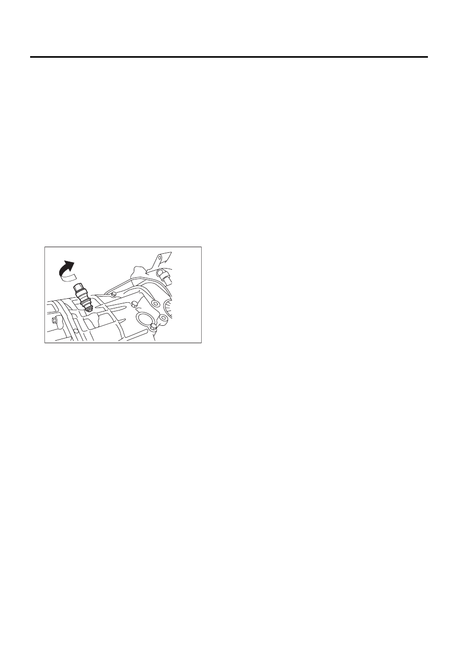
5) Disconnect connector from vehicle speed sen-
sor.
6) Turn and remove vehicle speed sensor.
B: INSTALLATION
NOTE:
• Discard vehicle speed sensor and after removal,
replace with a new one.
• Ensure sensor mounting hole is clean and free of
foreign matter.
• Align tip end of key with key groove on end of
speedometer shaft during installation.
1) Hand tighten vehicle speed sensor.
2) Tighten vehicle speed sensor using suitable tool.
Tightening torque:
5.9 N·m (0.6 kgf-m, 4.3 ft-lb)
3) Connect connector to vehicle speed sensor.
4) Install front, center exhaust pipes. (Non-TURBO
model)
Without OBD
<Ref. to EX(H4SOw/oOBD)-10, INSTALLATION,
Front Exhaust Pipe.>
With OBD
<Ref. to EX(H4SO)-6, INSTALLATION, Front Ex-
haust Pipe.>
5) Install center exhaust pipes. (TURBO model)
<Ref. to EX(H4DOSTC)-8, INSTALLATION, Cen-
ter Exhaust Pipe.>
6) Lower the vehicle.
7) Connect battery ground cable.
C: INSPECTION
Inspect the vehicle speed sensor. <Ref. to IDI-18,
INSPECTION, Speedometer.>
MT-00113
MT-46
MANUAL TRANSMISSION AND DIFFERENTIAL
PREPARATION FOR OVERHAUL
8. Preparation for Overhaul
A: PROCEDURE
1) Clean oil, grease, dirt and dust from transmis-
sion.
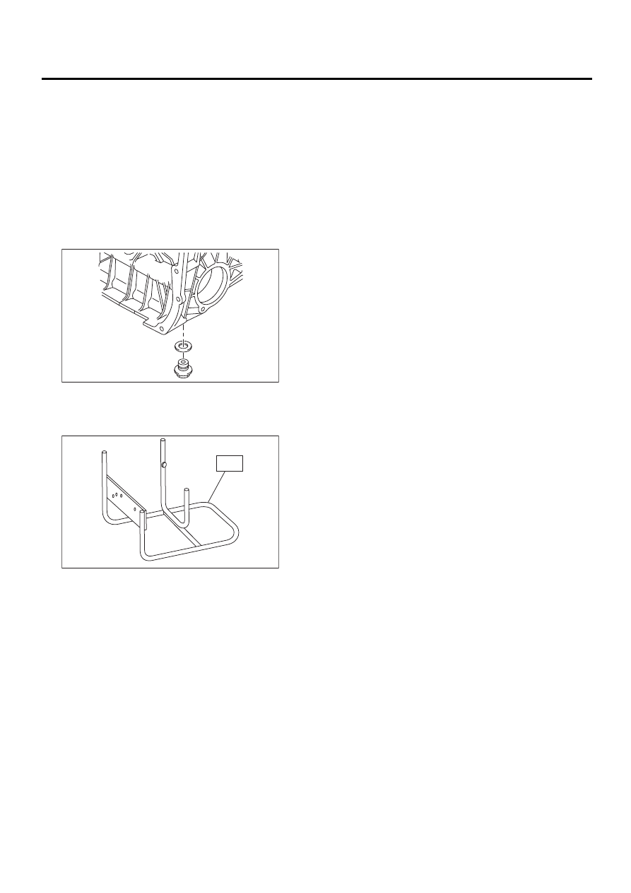
2) Remove drain plug to drain oil. After draining, re-
tighten it as before.
NOTE:
Replace gasket with a new one.
Tightening torque:
44 N·m (4.5 kgf-m, 32.5 ft-lb)
3) Attach transmission to ST.
ST
499937100
TRANSMISSION STAND
SET
4) Rotating parts should be coated with oil prior to
assembly.
5) All disassembled parts, if to be reused, should
be reinstalled in the original positions and direc-
tions.
6) Gaskets, lock washers and lock nut must be re-
placed with new ones.
7) Liquid gasket should be used where specified to
prevent leakage.
MT-00097
MT-00115
ST
MT-47
MANUAL TRANSMISSION AND DIFFERENTIAL
TRANSFER CASE AND EXTENSION CASE ASSEMBLY
9. Transfer Case and Extension
Case Assembly
A: REMOVAL
1) Remove the manual transmission assembly
from vehicle. <Ref. to MT-32, REMOVAL, Manual
Transmission Assembly.>
2) Remove back-up light switch and neutral posi-
tion switch. <Ref. to MT-42, REMOVAL, Switches
and Harness.>
3) Remove transfer case with extension case as-
sembly.
4) Remove shifter arm.
5) Remove extension case assembly.
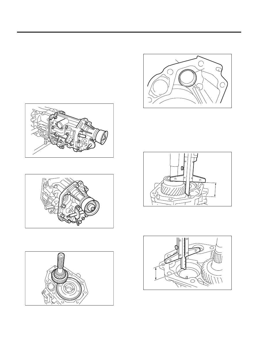
B: INSTALLATION
1) Install center differential and transfer driven gear
into transfer case.
2) Remove bearing cone from the extension case
assembly, and install to taper roller bearing of the
transfer driven gear.
3) While pressing the bearing cone horizontally,
turn the driven shaft ten rotations.
4) Measure height “W” between transfer case and
taper roller bearing on the transfer driven gear.
5) Measure depth “X”.
NOTE:
Measure with bearing cone and thrust washer re-
moved.
6) Calculate space “t” using the following equation:
t = X
−
W + 0.2 to 0.3 mm (0.008 to 0.012 in)
MT-00116
MT-00117
MT-00118
(A) Bearing cone (Extension case)
(B) Extension case
MT-00119
( A )
( B )
MT-00120
W
MT-00121
X
0
10
20
30
40
50
60
70
80
90
Нет комментариевНе стесняйтесь поделиться с нами вашим ценным мнением.
Текст