Subaru Legacy III (2000-2003 year). Service manual — part 257
ME(H6DO)-16
MECHANICAL
GENERAL DESCRIPTION
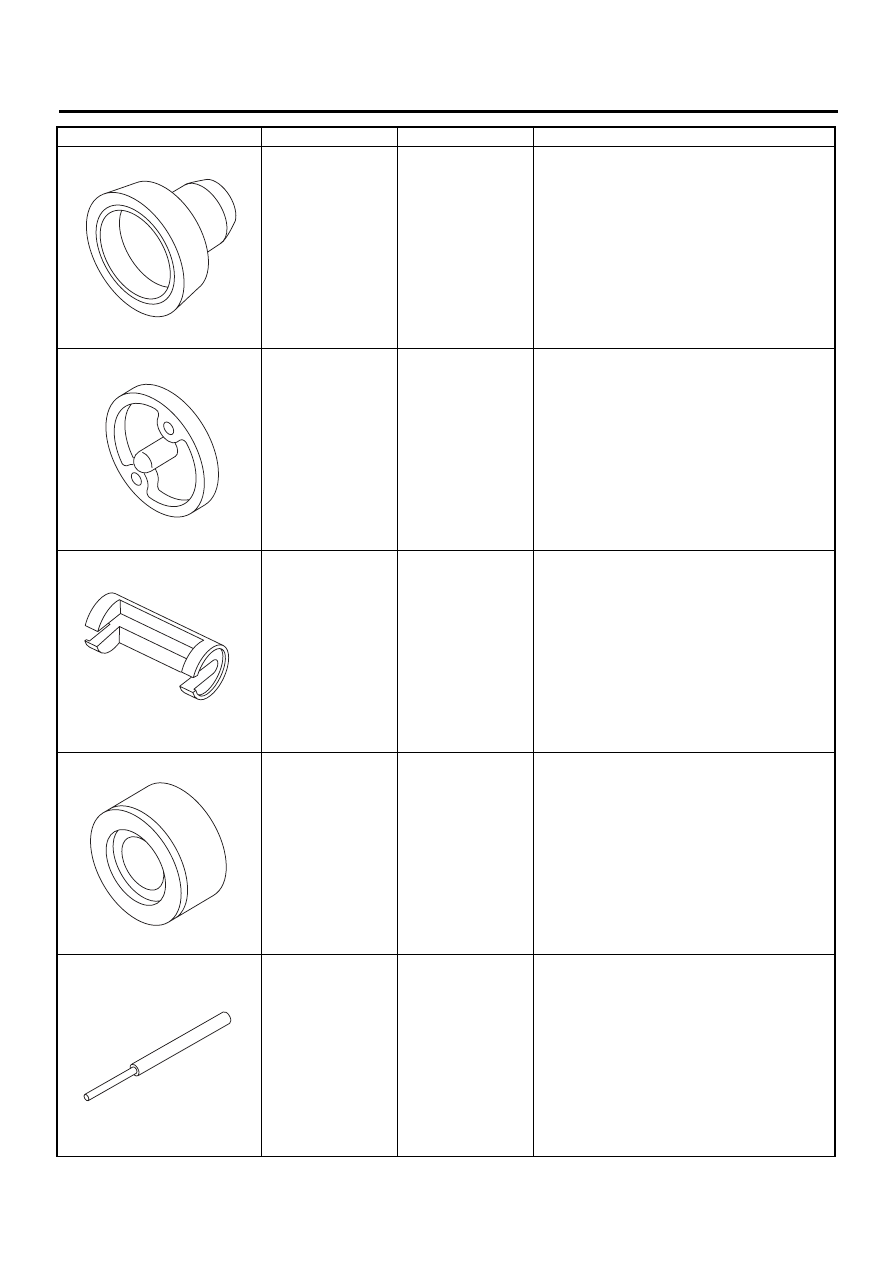
499587200
CRANKSHAFT OIL
SEAL INSTALLER
• Used for installing crankshaft oil seal.
• Used with CRANKSHAFT OIL SEAL GUIDE
(499597100).
499597100
CRANKSHAFT OIL
SEAL GUIDE
• Used for installing crankshaft oil seal.
• Used with CRANKSHAFT OIL SEAL
INSTALLER (499587200).
499718000
VALVE SPRING
REMOVER
Used for removing and installing valve spring.
18251AA000
VALVE GUIDE
ADJUSTER
Used for installing valve guides.
499765700
VALVE GUIDE
REMOVER
Used for removing valve guides.
ILLUSTRATION
TOOL NUMBER
DESCRIPTION
REMARKS
ST-499587200
ST-499597100
ST-499718000
ST18251AA000
ST-499765700
ME(H6DO)-17
MECHANICAL
GENERAL DESCRIPTION
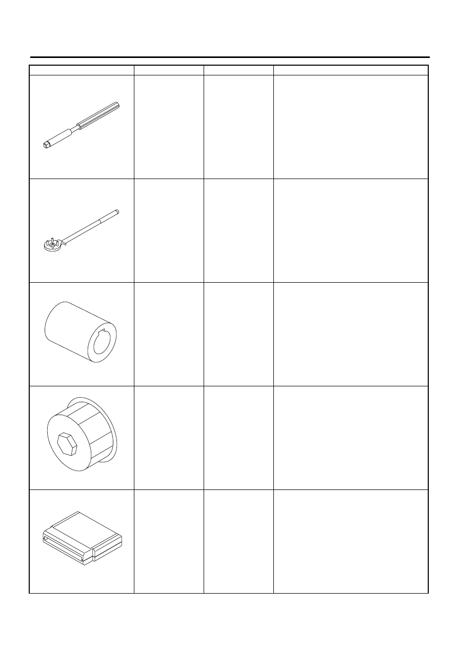
499765900
VALVE GUIDE
REAMER
Used for reaming valve guides.
499977100
CRANK PULLEY
WRENCH
Used for stopping rotation of crankshaft pulley
when loosening and tightening crankshaft pulley
bolts.
18252AA000
CRANKSHAFT
SOCKET
Used for rotating crankshaft.
498547000
OIL FILTER
WRENCH
Used for removing and installing oil filter.
24082AA210
(Newly adopted tool)
CARTRIDGE
Troubleshooting for electrical systems.
ILLUSTRATION
TOOL NUMBER
DESCRIPTION
REMARKS
ST-499765900
ST-499977100
ST18252AA000
ST-498547000
ST24082AA210
ME(H6DO)-18
MECHANICAL
GENERAL DESCRIPTION
2. GENERAL PURPOSE TOOLS
E: PROCEDURE
It is possible to conduct the following service proce-
dures with engine on the vehicle, however, the pro-
cedures described in this section are based on the
condition that the engine is removed from the vehi-
cle.
• Camshaft
• Cylinder Head
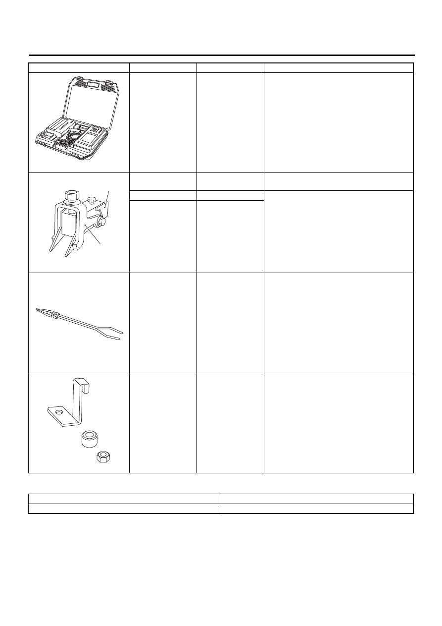
22771AA020
SELECT MONITOR
KIT
Troubleshooting for electrical systems.
• English:
22771AA020 (With printer)
22771AA030 (Without printer)
18329AA000
SHIM REPLACER
ASSY
Used for correct valve clearance.
A: 18330AA010
LIFTER
If 498187200 SHIM REPLACER ASSY (H4) tool
is available, it is commonly used for H6 by par-
tially replacing the following parts:
• LIFTER (H4)
→
LIFTER (H6) A: 18330AA010
• SLIDER (H4)
→
SLIDER (H6) B: 18351AA000
B: 18351AA000
SLIDER
18233AA000
PISTON PIN CIR-
CLIP PLIERS
Used for removing piston pin circlip.
498277200
STOPPER SET
Used for installing automatic transmission
assembly to engine.
TOOL NAME
REMARKS
Compression gauge
Used for measuring compression.
ILLUSTRATION
TOOL NUMBER
DESCRIPTION
REMARKS
ST22771AA020
ST18329AA000
( B )
( A )
ST18233AA000
ST-498277200

ME(H6DO)-19
MECHANICAL
COMPRESSION
2. Compression
A: INSPECTION
CAUTION:
After warming-up, engine becomes very hot. Be
careful not to burn yourself during measure-
ment.
1) After warming-up the engine, turn ignition switch
to OFF.
2) Make sure that the battery is fully charged.
3) Release fuel pressure. <Ref. to FU(H6DO)-50,
RELEASING OF FUEL PRESSURE, OPERA-
TION, Fuel.>
4) Remove all the spark plugs. <Ref. to IG(H6DO)-
4, REMOVAL, Spark Plug.>
5) Check the starter motor for satisfactory perfor-
mance and operation.
6) Hold the compression gauge tight against the
spark plug hole.
CAUTION:
When using a screw-in type compression
gauge, the screw (put into cylinder head spark
plug hole) should be less than 18 mm (0.71 in)
long.
7) Fully open throttle valve.
8) Crank the engine by means of the starter motor,
and read the maximum value on the gauge when
the pointer is steady.
9) Perform at least two measurements per cylinder,
and make sure that the values are correct.
Compression (350 rpm and fully open throttle):
Standard;
1,275 — 1,471 kPa (13.0 — 15.0 kg/cm
2
, 185
— 213 psi)
Limit;
1,128 kPa (11.5 kg/cm
2
, 164 psi)
ME-00446
Нет комментариевНе стесняйтесь поделиться с нами вашим ценным мнением.
Текст