Subaru Legacy III (2000-2003 year). Service manual — part 429
ME(H4DOSTC)-80
MECHANICAL
CYLINDER BLOCK
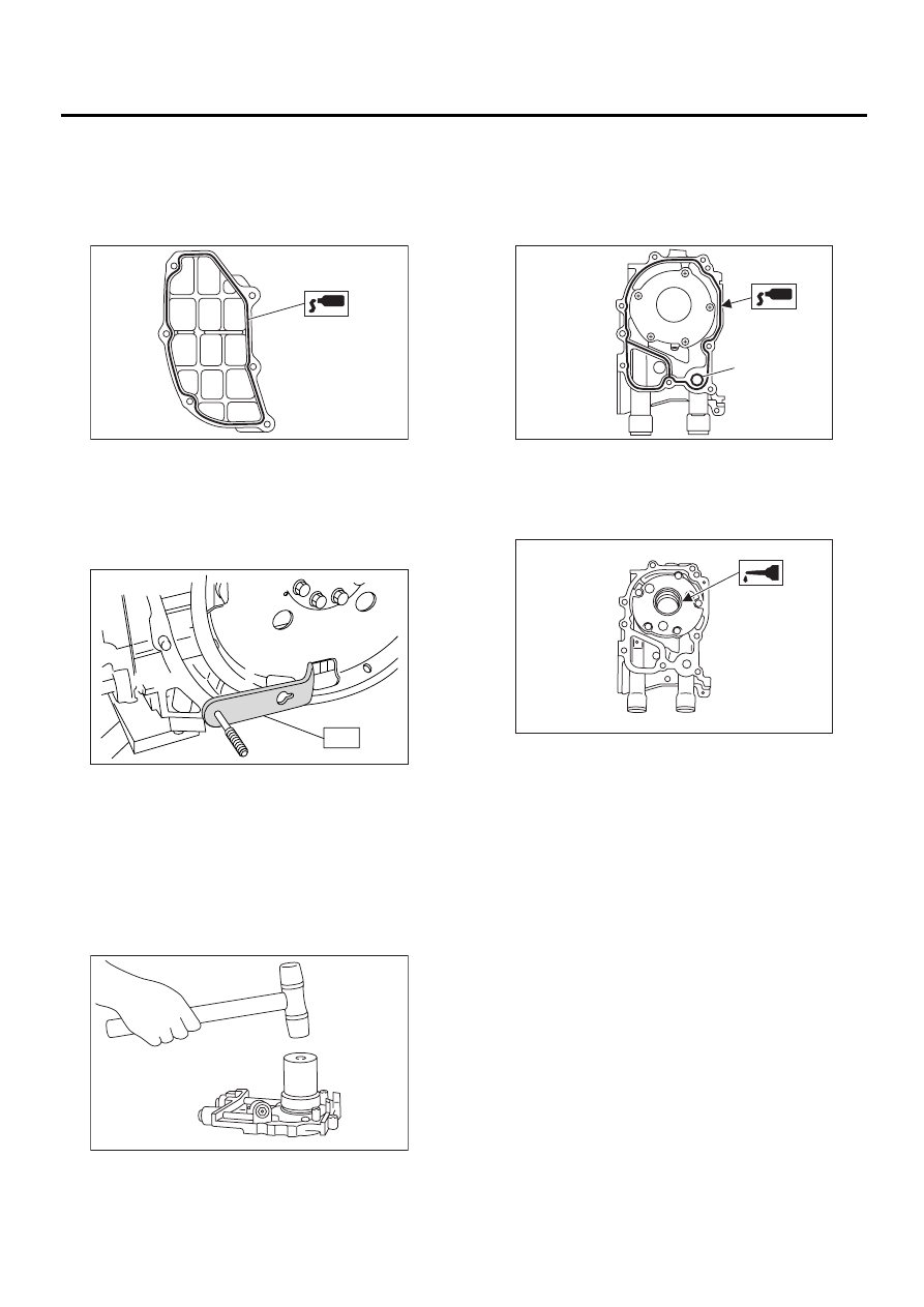
22) Apply fluid packing to the matching surfaces,
and then install the oil separator cover.
Fluid packing:
Part No. 004403007
THREE BOND 1215 or equivalent
23) Install the drive plate. (AT vehicles)
To lock the crankshaft, use ST.
ST
498497100
CRANKSHAFT STOPPER
Tightening torque:
7.2 N·m (7.3 kgf-m, 52.8 ft-lb)
24) Install the flywheel. (MT vehicles) <Ref. to CL-
20, INSTALLATION, Flywheel.>
25) Install the clutch disc and cover. (MT vehicles)
<Ref. to CL-15, INSTALLATION, Clutch Disc and
Cover.>
26) Installation of oil pump:
(1) Discard the front oil seal after removal. Re-
place with a new one using the ST.
ST
499587100
OIL SEAL INSTALLER
(2) Apply fluid packing to the matching surface
of oil pump.
Fluid packing:
Part No. 004403007
THREE BOND 1215 or equivalent
(3) Apply a coat of engine oil to the inside of the
oil seal.
(4) Install the oil pump on cylinder block. Be
careful not to damage the oil seal during instal-
lation.
Tightening torque:
6.4 N·m (0.65 kgf-m, 4.7 ft-lb)
NOTE:
• Do not forget to install the O-ring and seal when
installing the oil pump.
• Align the flat surface of oil pump's inner rotor with
crankshaft before installation.
ME-00163
ME-00136
ST
ME-00164
(A) O-ring
( A )
ME-00165
ME-00312
ME(H4DOSTC)-81
MECHANICAL
CYLINDER BLOCK
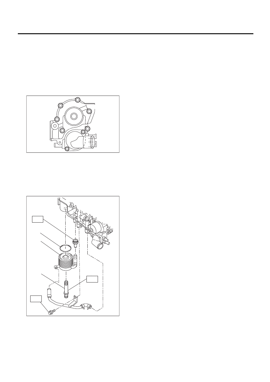
27) Install the water pump and gasket.
Tightening torque:
First; 12 N·m (1.2 kgf-m, 8.7 ft-lb)
Second; 12 N·m (1.2 kgf-m, 8.7 ft-lb)
NOTE:
• Be sure to use a new gasket.
• When installing the water pump, tighten bolts in
two stages in alphabetical sequence as shown in
the figure.
28) Install the water by-pass pipe for heater.
29) Install the oil cooler.
Tightening torque:
T1: 55 N·m (5.5 kgf-m, 40 ft-lb)
T2: 69 N·m (7.0 kgf-m, 50.6 ft-lb)
T3: 6.4 N·m (0.65 kgf-m, 4.7 ft-lb)
30) Install the oil filter using ST.
ST
18332AA000
OIL FILTER WRENCH
31) Install the water by-pass pipe between oil cool-
er and water pump.
32) Install the water pipe.
NOTE:
Always use a new O-ring.
33) Install the cylinder head assembly.
<Ref. to ME(H4DOSTC)-62, INSTALLATION,
CYLINDER HEAD ASSEMBLY.>
34) Install the oil level gauge guide and tighten the
attaching bolt (left side only).
35) Install the rocker cover.
36) Install the crankshaft sprocket.
<Ref. to ME(H4DOSTC)-56, INSTALLATION,
Crankshaft Sprocket.>
37) Install the camshaft sprocket.
<Ref. to ME(H4DOSTC)-55, INSTALLATION,
Camshaft Sprocket.>
38) Install the timing belt assembly.
<Ref. to ME(H4DOSTC)-49, INSTALLATION, Tim-
ing Belt Assembly.>
39) Install the belt cover.
<Ref. to ME(H4DOSTC)-46, INSTALLATION, Belt
Cover.>
40) Install the crankshaft pulley.
<Ref. to ME(H4DOSTC)-44, INSTALLATION,
Crankshaft Pulley.>
41) Install the generator and A/C compressor
brackets on cylinder head.
42) Install the V-belt.
<Ref. to ME(H4DOSTC)-42, INSTALLATION, V-
belt.>
43) Install the intake manifold.
<Ref. to FU(H4DOSTC)-18, INSTALLATION, In-
take Manifold.>
(A) O-ring
(B) Oil cooler
(C) Oil cooler connector
( A )
( B )
( C )
( D )
( E )
( F )
ME-00167
ME-00640
( A )
( B )
( C )
T1
T3
T2
ME(H4DOSTC)-82
MECHANICAL
CYLINDER BLOCK
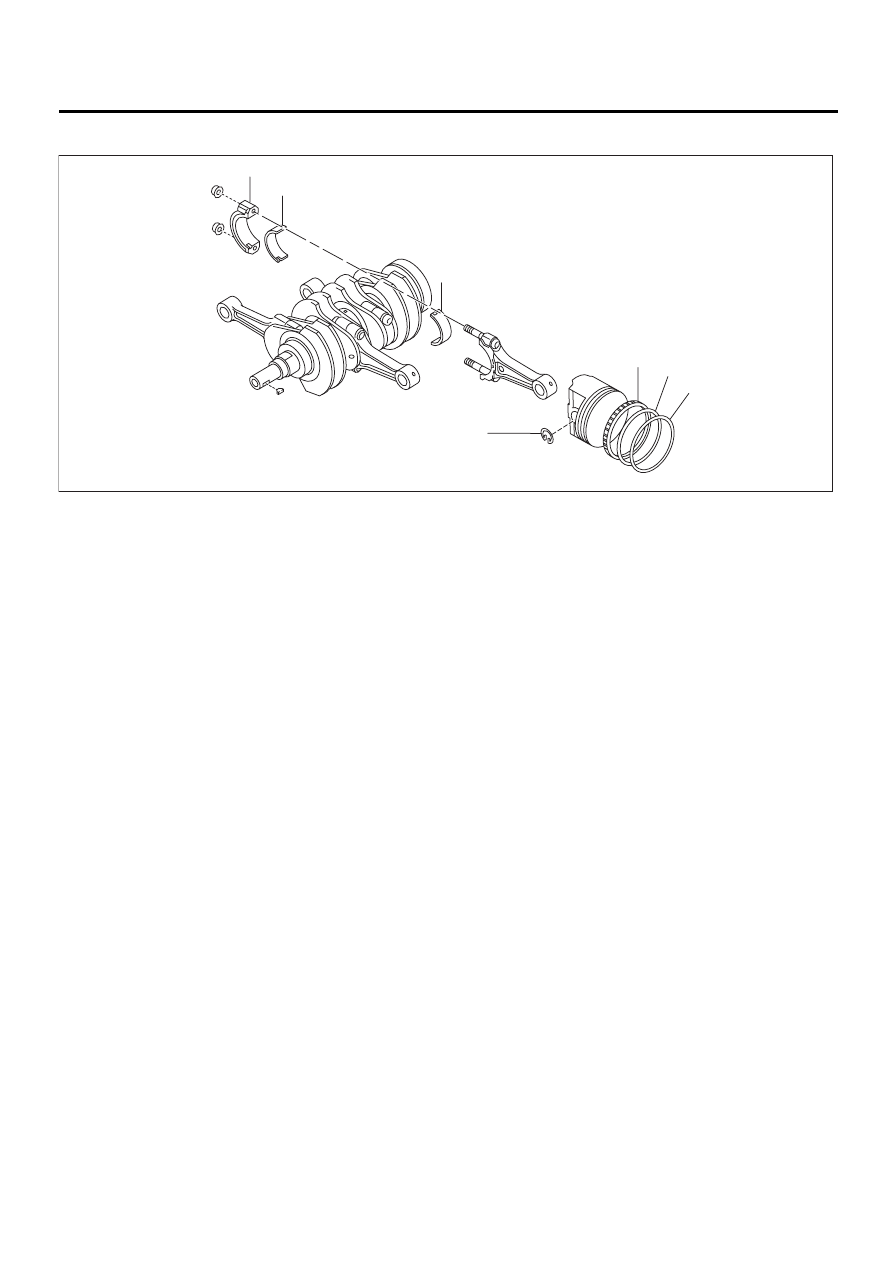
C: DISASSEMBLY
1) Remove the connecting rod cap.
2) Remove the connecting rod bearing.
NOTE:
Arrange the removed connecting rod, connecting
rod cap and bearing in order to prevent confusion.
3) Remove the piston rings using the piston ring ex-
pander.
4) Remove the oil ring by hand.
NOTE:
Arrange the removed piston rings in proper order to
prevent confusion.
5) Remove the circlip.
(1) Connecting rod cap
(3) Top ring
(5) Oil ring
(2) Connecting rod bearing
(4) Second ring
(6) Circlip
( 3 )
( 4 )
( 5 )
( 6 )
( 2 )
( 2 )
( 1 )
ME-00168
ME(H4DOSTC)-83
MECHANICAL
CYLINDER BLOCK
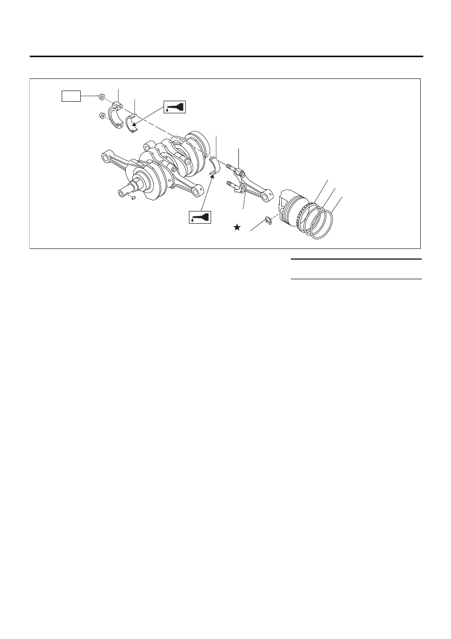
D: ASSEMBLY
1) Apply oil to the surfaces of the connecting rod
bearings. Install the connecting rod bearings on
connecting rods and connecting rod caps.
2) Install the connecting rod on crankshaft.
NOTE:
Position each connecting rod with the side marked
facing forward.
3) Install the connecting rod cap with connecting
rod nut.
Ensure the arrow on connecting rod cap faces the
front during installation.
NOTE:
• Each connecting rod has its own mating cap.
Make sure that they are assembled correctly by
checking their matching number.
• When tightening the connecting rod nuts, apply
oil on the threads.
4) Install the oil ring spacer, upper rail and lower rail
in this order by hand. Then install the second ring
and top ring with a piston ring expander.
E: INSPECTION
1. CYLINDER BLOCK
1) Visually check for cracks and damage. Especial-
ly, inspect the important parts by means of red lead
check.
2) Check the oil passages for clogging.
3) Inspect the crankcase surface that mates with
cylinder head for warping by using a straight edge,
and correct by grinding if necessary.
Warping limit:
0.05 mm (0.0020 in)
Grinding limit:
0.1 mm (0.004 in)
Standard height of cylinder block:
201.0 mm (7.91 in)
2. CYLINDER AND PISTON
1) The cylinder bore size is stamped on cylinder
block's front upper surface.
NOTE:
Measurement should be performed at a tempera-
ture of 20
°
C (60
°
F).
NOTE:
Standard sized pistons are classified into two
grades, “A” and “B”. These grades should be used
as a guide line in selecting a standard piston.
(1) Connecting rod bearing
(5) Second ring
Tightening torque: N·m (kgf-m, ft-lb)
(2) Connecting rod
(6) Top ring
T: 45 (4.6, 33)
(3) Connecting rod cap
(7) Circlip
(4) Oil ring
(8) Side mark
( 2 )
( 7 )
( 4 )
( 5 )
( 6 )
( 1 )
( 1 )
ME-00169
( 3 )
T
( 8 )
Нет комментариевНе стесняйтесь поделиться с нами вашим ценным мнением.
Текст