Subaru Legacy III (2000-2003 year). Service manual — part 996
CC-4
CRUISE CONTROL SYSTEM (DIAGNOSTICS)
GENERAL DESCRIPTION
2. General Description
A: CAUTION
1. SUPPLEMENTAL RESTRAINT SYSTEM
“AIRBAG”
Airbag system wiring harness is routed near the
cruise control module and cruise control command
switch.
CAUTION:
• All airbag system wiring harness and con-
nectors are colored yellow. Do not use electri-
cal test equipment on these circuits.
• Be careful not to damage airbag system wir-
ing harness when servicing the cruise control
module and cruise control command switch.
CC-5
CRUISE CONTROL SYSTEM (DIAGNOSTICS)
GENERAL DESCRIPTION
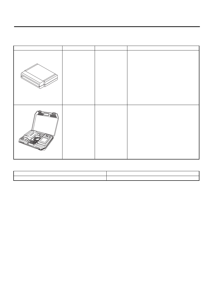
B: PREPARATION TOOL
1. SPECIAL TOOLS
2. GENERAL TOOLS
ILLUSTRATION
TOOL NUMBER
DESCRIPTION
REMARKS
24082AA210 (Newly
adopted tool)
CARTRIDGE
Troubleshooting for electrical systems.
22771AA030
SUBARU SELECT
MONITOR KIT
Troubleshooting for electrical systems.
• English:
22771AA030 (Without printer)
• German:
22771AA070 (Without printer)
• French:
22771AA080 (Without printer)
• Spanish:
22771AA090 (Without printer)
TOOL NAME
REMARKS
Circuit Tester
Used for measuring resistance, voltage and ampere.
ST24082AA210
ST22771AA030
CC-6
CRUISE CONTROL SYSTEM (DIAGNOSTICS)
GENERAL DESCRIPTION
C: INSPECTION
1. BATTERY
Measure battery voltage and specific gravity of
electrolyte.
Standard voltage:
12 V, or more
Specific gravity:
Above 1.260
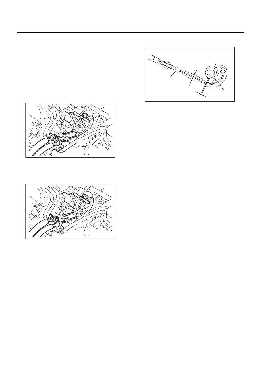
2. CRUISE CONTROL CABLE
Check the cruise control cable (B) installation.
If NG, install the cable securely.
3. ACCELERATOR CABLE
Check movement of the accelerator cable (A) when
the cruise control throttle is moved by hand.
If NG, check throttle cam.
4. THROTTLE CAM
Check that the throttle cam moves smoothly.
If NG, repair throttle cam.
5. CABLE FREE PLAY
Check that the clearance (A) between throttle cam
(B) and lever or cable deflection (D) is within spec-
ifications.
Throttle cam-to-lever clearance:
0 — 1 mm (0 — 0.04 in)
Inner cable deflection:
1 — 8 mm (0.04 — 0.31 in)
If NG, adjust the clearance or the deflection with
the adjust nut.
NOTE:
Check that the cap (C) is positioned in the groove.
CC-00156
( A )
( B )
CC-00156
( A )
( B )
CC-00037
(B)
(A)
(D)
(C)
CC-7
CRUISE CONTROL SYSTEM (DIAGNOSTICS)
ELECTRICAL COMPONENTS LOCATION
3. Electrical Components Location
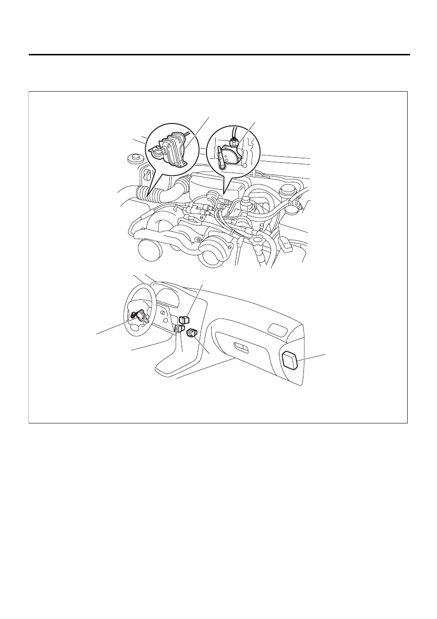
A: LOCATION
NOTE:
Electrical component locations are for LHD vehicles.
Cruise control actuator and cruise control module locations for RHD vehicles are symmetrically opposite.
Cruise control main switch location is different depending on destination.
CC-00095
( 1 )
( 2 )
( 3 )
( 4 )
( 5 )
( 6 )
( 7 )
(1) Actuator
(4) Cruise control main switch
(7) Cruise control module
(2) Inhibitor switch (AT)
(5) Clutch switch (MT)
(3) Cruise control command switch
(6) Stop and brake switch
Нет комментариевНе стесняйтесь поделиться с нами вашим ценным мнением.
Текст