Subaru Legacy III (2000-2003 year). Service manual — part 68
ME(H4SO)-84
MECHANICAL
CYLINDER BLOCK
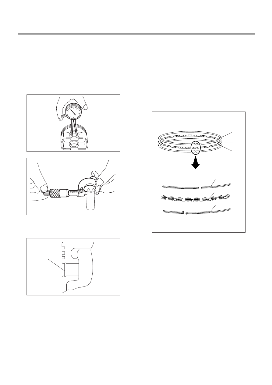
3) Make sure that piston pin can be inserted into
piston pin hole with a thumb at 20
°
C (68
°
F). Re-
place if defective.
Standard clearance between piston pin and
hole in piston:
Standard
0.004 — 0.008 mm (0.0002 — 0.0003 in)
Limit
0.020 mm (0.0008 in)
4) Check the circlip installation groove on piston for
burr (A). If necessary, remove the burr from groove
so that piston pin can lightly move.
5) Check the piston pin circlip for distortion, cracks
and wear.
4. PISTON RING
1) If the piston ring is broken, damaged, or worn, or
if its tension is insufficient, or when the piston is re-
placed, replace the piston ring with a new one of
the same size as the piston.
NOTE:
• Marks are shown on the end of top and second
rings. When installing the rings to piston, face these
marks upward.
• Oil ring is composed of upper rail, expander and
lower rail. Be careful of the rail direction when in-
stalling oil ring to the piston.
2) Clean the piston ring groove and piston ring.
ME-00173
0
0
5
5
10
10
15
ME-00174
ME-00175
( A )
(A) Upper rail
(B) Expander
(C) Lower rail
ME-00375
(A)
(B)
(C)
(A)
(B)
(C)
ME(H4SO)-85
MECHANICAL
CYLINDER BLOCK
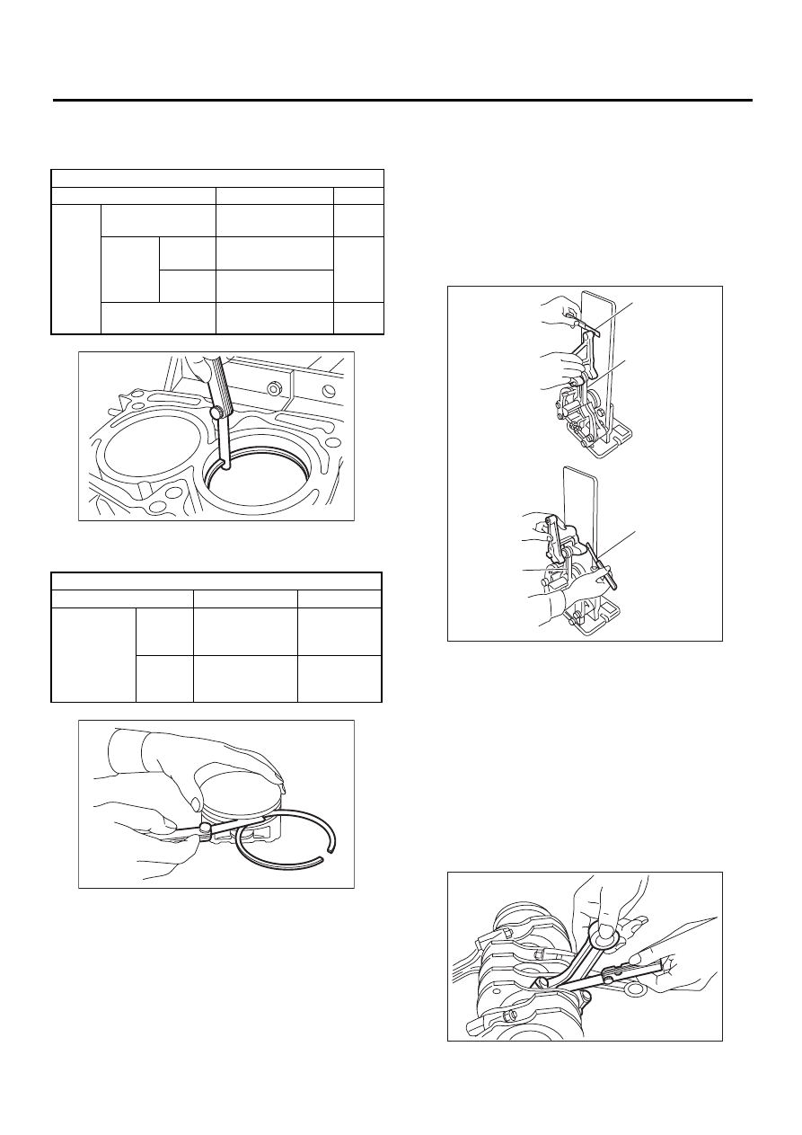
3) Squarely place the piston ring and oil ring in cyl-
inder, and then measure the piston ring gap with a
thickness gauge.
4) Measure the clearance between piston ring and
piston ring groove with a thickness gauge.
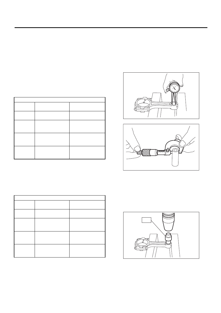
5. CONNECTING ROD
1) Replace the connecting rod, if the large or small
end thrust surface is damaged.
2) Check for bend or twist using a connecting rod
aligner. Replace the connecting rod if the bend or
twist exceeds the limit.
Limit of bend or twist per 100 mm (3.94 in) in
length:
0.10 mm (0.0039 in)
3) Install the connecting rod fitted with bearing to
crankshaft, and then measure the side clearance
(thrust clearance). Replace the connecting rod if
the side clearance exceeds the specified limit.
Connecting rod side clearance:
Standard
0.070 — 0.330 mm (0.0028 — 0.0130 in)
Limit
0.4 mm (0.016 in)
Unit: mm (in)
Standard
Limit
Piston
ring
gap
Top ring
0.20 — 0.35
(0.0079 — 0.0138)
1.0
(0.039)
Second
ring
2000 cc
0.35 — 0.50
(0.0138 — 0.0197)
1.0
(0.039)
2500 cc
0.37 — 0.52
(0.0146 — 0.0204)
Oil ring rail
0.20 — 0.50
(0.0079 — 0.0197)
1.5
(0.059)
Unit: mm (in)
Standard
Limit
Clearance
between pis-
ton ring and
piston ring
groove
Top ring
0.040 — 0.080
(0.0016 —
0.0031)
0.15 (0.0059)
Second
ring
0.030 — 0.070
(0.0012 —
0.0028)
0.15 (0.0059)
ME-00177
ME-00178
(A) Thickness gauge
(B) Connecting rod
( A )
( B )
( A )
( B )
ME-00179
ME-00180
ME(H4SO)-86
MECHANICAL
CYLINDER BLOCK
4) Inspect the connecting rod bearing for scar,
peeling, seizure, melting, wear, etc.
5) Measure the oil clearance on individual connect-
ing rod bearings by means of plastigauge. If any oil
clearance is not within specification, replace the
defective bearing with a new one of standard size
or undersize as necessary. (See the table below.)
Connecting rod oil clearance:
• 2000 cc MODEL
Standard
0.010 — 0.038 mm (0.0004 — 0.0015 in)
Limit
0.050 mm (0.0020 in)
Connecting rod oil clearance:
• 2500 cc MODEL
Standard
0.012 — 0.038 mm (0.0005 — 0.0015 in)
Limit
0.05 mm (0.0020 in)
6) Inspect the bushing at connecting rod small end,
and replace if worn or damaged. Also measure the
piston pin clearance at connecting rod small end.
Clearance between piston pin and bushing:
Standard
0 — 0.022 mm (0 — 0.0009 in)
Limit
0.030 mm (0.0012 in)
7) Replacement procedure is as follows.
(1) Remove the bushing from connecting rod
with ST and press.
(2) Press the bushing with ST after applying oil
on the periphery of bushing.
ST
499037100
CONNECTING ROD BUSH-
ING REMOVER AND IN-
STALLER
(3) Make two 3 mm (0.12 in) holes in bushing.
Ream the inside of bushing.
(4) After the completion of reaming, clean the
bushing to remove chips.
Unit: mm (in)
Bearing
Bearing size
(Thickness at center)
Outer diameter of
crank pin
Standard
1.492 — 1.501
(0.0587 — 0.0591)
51.984 — 52.000
(2.0466 — 2.0472)
0.03
(0.0012)
undersize
1.510 — 1.513
(0.0594 — 0.0596)
51.954 — 51.970
(2.0454 — 2.0461)
0.05
(0.0020)
undersize
1.520 — 1.523
(0.0598 — 0.0600)
51.934 — 51.950
(2.0446 — 2.0453)
0.25
(0.0098)
undersize
1.620 — 1.623
(0.0638 — 0.0639)
51.734 — 51.750
(2.0368 — 2.0374)
Unit: mm (in)
Bearing
Bearing size
(Thickness at center)
Outer diameter of
crank pin
Standard
1.490 — 1.502
(0.0587 — 0.0591)
51.984 — 52.000
(2.0466 — 2.0472)
0.03
(0.0012)
undersize
1.504 — 1.512
(0.0592 — 0.0595)
51.954 — 51.970
(2.0454 — 2.0461)
0.05
(0.0020)
undersize
1.514 — 1.522
(0.0596 — 0.0599)
51.934 — 51.950
(2.0446 — 2.0453)
0.25
(0.0098)
undersize
1.614 — 1.622
(0.0635 — 0.0639)
51.734 — 51.750
(2.0368 — 2.0374)
ME-00181
0
0
5
5
10
10
15
ME-00174
ME-00182
ST
ME(H4SO)-87
MECHANICAL
CYLINDER BLOCK
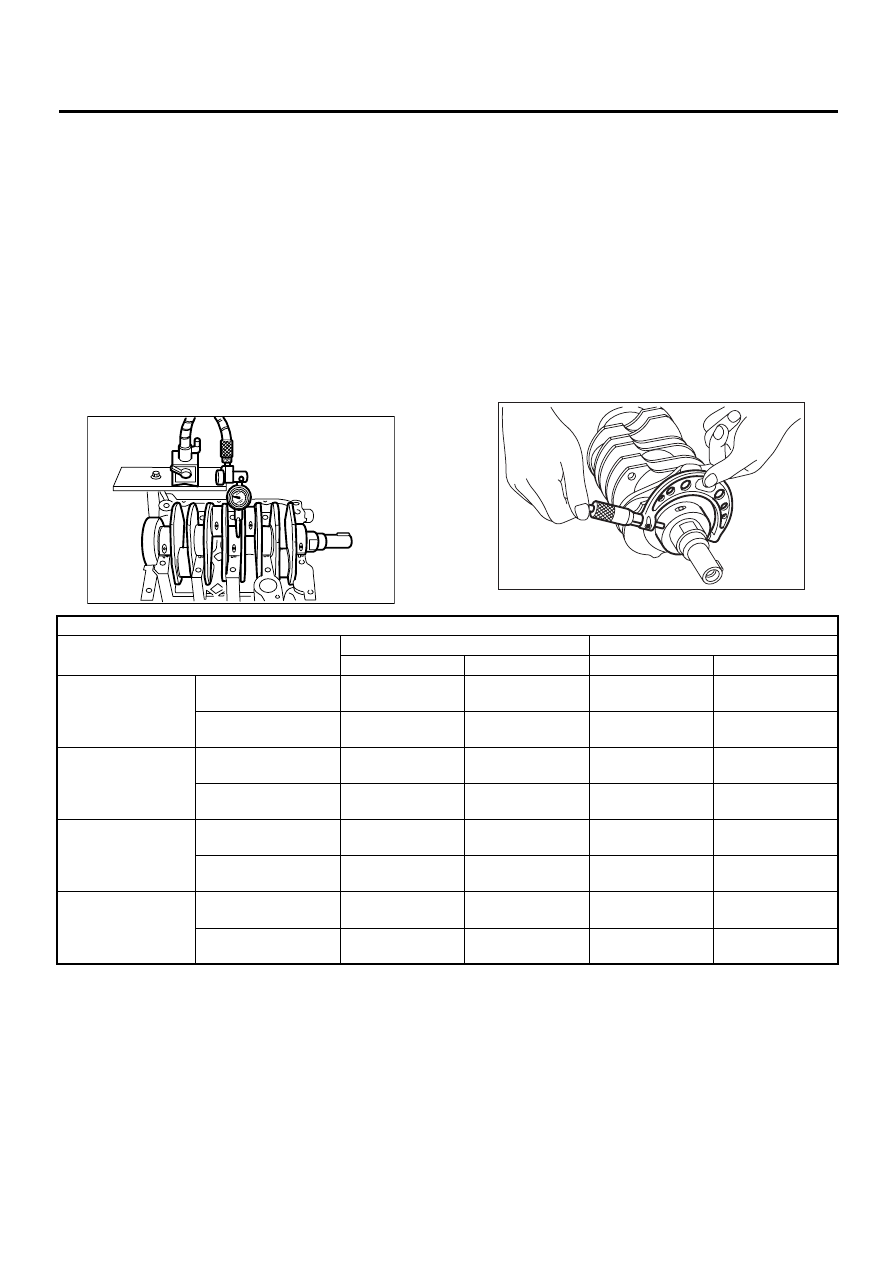
6. CRANKSHAFT AND CRANKSHAFT
BEARING
1) Clean the crankshaft completely and check for
cracks by means of red lead check etc., and re-
place if defective.
2) Measure the crankshaft bend, and correct or re-
place if it exceeds the limit.
NOTE:
If a suitable V-block is not available, install the #1
and #5 crankshaft bearing on cylinder block, posi-
tion the crankshaft on these bearings and measure
the crankshaft bend using a dial gauge.
Crankshaft bend limit:
0.035 mm (0.0014 in)
3) Inspect the crank journal and crank pin for wear.
If they are not within the specifications, replace the
bearing with a suitable (undersize) one, and then
replace or recondition the crankshaft as necessary.
When grinding the crank journal or crank pin, finish
them to specified dimensions according to the un-
dersize bearing to be used.
Crank pin and crank journal:
Out-of-roundness
0.020 mm (0.0008 in) or less
Taper limit
0.07 mm (0.0028 in)
Grinding limit
0.250 mm (0.0098 in)
O.D. ... Outer Diameter
ME-00183
ME-00184
Unit: mm (in)
Crank journal diameter
Crank pin diameter
#1, #3
#2, #4, #5
2000 cc
2500 cc
Standard
Journal O.D.
59.992 — 60.008
(2.3619 — 2.3625)
59.992 — 60.008
(2.3619 — 2.3625)
51.984 — 52.000
(2.0466 — 2.0472)
51.984 — 52.000
(2.0466 — 2.0472)
Bearing size
(Thickness at center)
1.998 — 2.011
(0.0787 — 0.0792)
2.000 — 2.013
(0.0787 — 0.0793)
1.492 — 1.501
(0.0587 — 0.0591)
1.490 — 1.502
(0.0587 — 0.0591)
0.03 (0.0012)
undersize
Journal O.D.
59.962 — 59.978
(2.3607 — 2.3613)
59.962 — 59.978
(2.3607 — 2.3613)
51.954 — 51.970
(2.0454 — 2.0461)
51.954 — 51.970
(2.0454 — 2.0461)
Bearing size
(Thickness at center)
2.017 — 2.020
(0.0794 — 0.0795)
2.019 — 2.022
(0.0795 — 0.0796)
1.510 — 1.513
(0.0594 — 0.0596)
1.504 — 1.512
(0.0592 — 0.0595)
0.05 (0.0020)
undersize
Journal O.D.
59.942 — 59.958
(2.3599 — 2.3605)
59.942 — 59.958
(2.3599 — 2.3605)
51.934 — 51.950
(2.0446 — 2.0453)
51.934 — 51.950
(2.0446 — 2.0453)
Bearing size
(Thickness at center)
2.027 — 2.030
(0.0798 — 0.0799)
2.029 — 2.032
(0.0799 — 0.0800)
1.520 — 1.523
(0.0598 — 0.0600)
1.514 — 1.522
(0.0596 — 0.0599)
0.25 (0.0098)
undersize
Journal O.D.
59.742 — 59.758
(2.3520 — 2.3527)
59.742 — 59.758
(2.3520 — 2.3527)
51.734 — 51.750
(2.0368 — 2.0374)
51.734 — 51.750
(2.0368 — 2.0374)
Bearing size
(Thickness at center)
2.127 — 2.130
(0.0837 — 0.0839)
2.129 — 2.132
(0.0838 — 0.0839)
1.620 — 1.623
(0.0638 — 0.0639)
1.614 — 1.622
(0.0635 — 0.0639)
Нет комментариевНе стесняйтесь поделиться с нами вашим ценным мнением.
Текст