Subaru Legacy III (2000-2003 year). Service manual — part 121
EN(H4SO)-96
ENGINE (DIAGNOSTICS)
DIAGNOSTIC PROCEDURE WITH DIAGNOSTIC TROUBLE CODE (DTC)
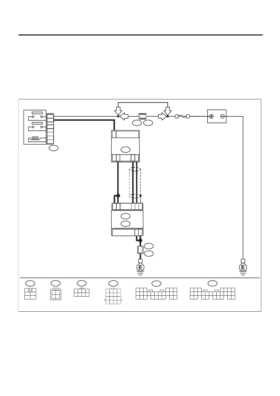
C: DTC P0032 — HO2S HEATER CONTROL CIRCUIT HIGH (BANK 1 SENSOR
1) —
• DTC DETECTING CONDITION:
• Two consecutive driving cycles with fault
CAUTION:
After repair or replacement of faulty parts, conduct Clear Memory Mode<Ref. to EN(H4SO)-47, OPER-
ATION, Clear Memory Mode.> and Inspection Mode <Ref. to EN(H4SO)-40, OPERATION, Inspection
Mode.> .
• WIRING DIAGRAM:
EN-01144
F44
B61
6
RHD
RHD
BATTERY
SBF-5
B47
MAIN RELAY
1
2
3
5
4
6
F44
1 2 3 4
5 6 7 8
C16
C5
4
8
B22
E3
ECM
C6
C17
C22
C13
B23
3
2
1
FRONT OXYGEN
(A/F) SENSOR
B18
B135
B:
B136
C:
B22
1 2 3 4
5 6 7 8
9 10 11 12
13 14 15 16
B47
3
4
5
6
1
2
B136
5 6
7
2
1
9
8
4
3
23
21 22
24
10 11 12 13 14
25 26
15 16 17
18 19 20
B18
4
2 1
3
LHD
LHD
5 6 7
8
2
1
9
4
3
10
24
22 23
25
11 12 13 14 15
26
27 28
16 17 18 19
20 21
B135

EN(H4SO)-97
ENGINE (DIAGNOSTICS)
DIAGNOSTIC PROCEDURE WITH DIAGNOSTIC TROUBLE CODE (DTC)
Step
Value
Yes
No
1
CHECK OUTPUT SIGNAL FROM ECM.
1) Turn ignition switch to ON.
2) Measure voltage between ECM connector
and chassis ground.
Connector & terminal
(B136) No. 6 (+) — Chassis ground (
−−−−
):
(B136) No. 17 (+) — Chassis ground (
−−−−
):
Does the measured value exceed the spec-
ified value?
8 V
2
CHECK FRONT OXYGEN (A/F) SENSOR
HEATER CURRENT.
1) Turn ignition switch to OFF.
2) Repair battery short circuit in harness
between ECM and front oxygen (A/F) sen-
sor connector.
3) Turn ignition switch to ON.
4) Read data of front oxygen (A/F) sensor
heater current using Subaru Select Monitor
or the OBD-II general scan tool.
Does the measured value exceed the spec-
ified value?
NOTE:
•Subaru Select Monitor
For detailed operation procedure, refer to the
“READ CURRENT DATA FOR ENGINE”.
<Ref. to EN(H4SO)-32, Subaru Select Moni-
tor.>
•OBD-II general scan tool
For detailed operation procedure, refer to the
OBD-II General Scan Tool Instruction Manual.
2.3 A
Replace ECM.
<Ref. to
FU(H4SO)-45,
Engine Control
Module.>
END
3
CHECK OUTPUT SIGNAL FROM ECM.
Measure voltage between ECM connector and
chassis ground.
Connector & terminal
(B136) No. 6 (+) — Chassis ground (
−−−−
):
(B136) No. 17 (+) — Chassis ground (
−−−−
):
Does the measured value exceed the specified
value by shaking harness and connector of
ECM while monitoring the value?
8 V
Repair battery
short circuit in har-
ness between
ECM and front
oxygen (A/F) sen-
sor connector.
END
EN(H4SO)-98
ENGINE (DIAGNOSTICS)
DIAGNOSTIC PROCEDURE WITH DIAGNOSTIC TROUBLE CODE (DTC)
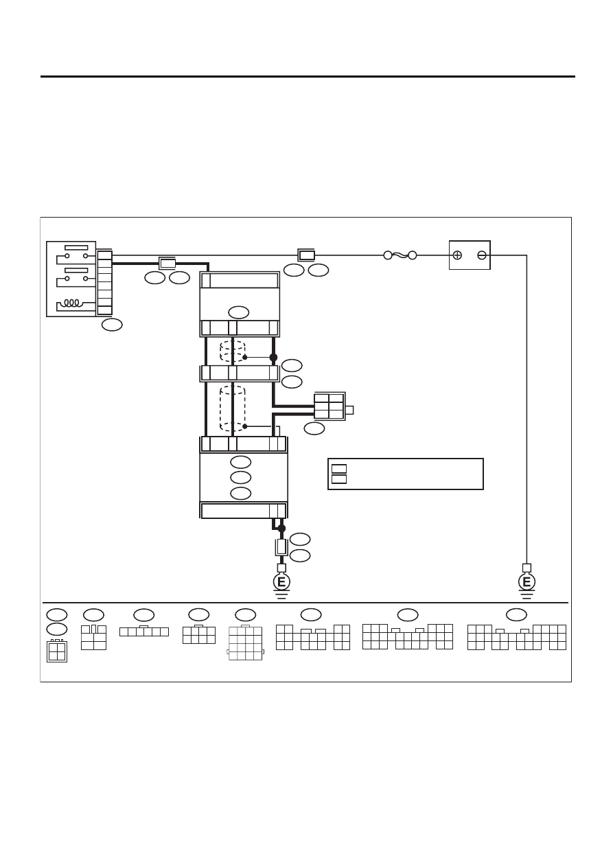
D: DTC P0037 — HO2S HEATER CONTROL CIRCUIT LOW (BANK 1 SENSOR 2)
—
• DTC DETECTING CONDITION:
• Two consecutive driving cycles with fault
CAUTION:
After repair or replacement of faulty parts, conduct Clear Memory Mode<Ref. to EN(H4SO)-47, OPER-
ATION, Clear Memory Mode.> and Inspection Mode <Ref. to EN(H4SO)-40, OPERATION, Inspection
Mode.> .
• WIRING DIAGRAM:
EN-01122
BATTERY
F44
B61
6
T5
B19
2
B47
MAIN RELAY
1
2
3
5
4
6
F44
1 2 3 4
5 6 7 8
C4
B14
B19
D15
C16
C5
REAR
OXYGEN SENSOR
ECM
4
1
3
1
4
3
2
8
B22
B83
B19
T5
T6
E3
B47
B19
B22
1 2 3 4
5 6 7 8
9 10 11 12
13 14 15 16
3
4
5
6
1
2
T6
4 3
2 1
2
1
FG
3
B135
B:
C: B136
D: B137
SBF-5
B136
5 6
7
2
1
9
8
4
3
23
21 22
24
10 11 12 13 14
25 26
15 16 17
18 19 20
B137
4
1
5
3
2
6
18
15
16
7 8 9 10 11
17
19 20
12 13
14
5 6 7
8
2
1
9
4
3
10
24
22 23
25
11 12 13 14 15
26
27 28
16 17 18 19
20 21
B135
B83
1 2 3 4 5 6
4
EG
: FOR G.C.C COUNTRIES MODEL
: EXCEPT FOR G.C.C COUNTRIES MODEL
FG
EG

EN(H4SO)-99
ENGINE (DIAGNOSTICS)
DIAGNOSTIC PROCEDURE WITH DIAGNOSTIC TROUBLE CODE (DTC)
Step
Value
Yes
No
1
CHECK GROUND CIRCUIT OF ECM.
1) Turn ignition switch to OFF.
2) Disconnect connector from ECM.
3) Measure resistance of harness between
ECM connector and chassis ground.
Connector & terminal
(B136) No. 5 — Chassis ground:
(B136) No. 16 — Chassis ground:
Is the measured value less than the speci-
fied value?
5
Ω
2
CHECK CURRENT DATA.
1) Start engine.
2) Read data of rear oxygen sensor heater
current using Subaru Select Monitor or
OBD-II general scan tool.
Does the measured value exceed the spec-
ified value?
NOTE:
•Subaru Select Monitor
For detailed operation procedure, refer to the
“READ CURRENT DATA FOR ENGINE”.
<Ref. to EN(H4SO)-32, Subaru Select Moni-
tor.>
•OBD-II scan tool
For detailed operation procedures, refer to the
OBD-II General Scan Tool Instruction Manual.
0.2 A
Repair connector.
NOTE:
In this case, repair
the following:
• Poor contact in
rear oxygen sen-
sor connector
• Poor contact in
rear oxygen sen-
sor connecting
harness connector
• Poor contact in
ECM connector
3
CHECK OUTPUT SIGNAL FROM ECM.
1) Start and idle the engine.
2) Measure voltage between ECM connector
and chassis ground.
Connector & terminal
(B136) No. 4 (+) — Chassis ground (
−−−−
):
Is the measured value less than the speci-
fied value?
1.0 V
4
CHECK OUTPUT SIGNAL FROM ECM.
Measure voltage between ECM connector and
chassis ground.
Connector & terminal
(B136) No. 4 (+) — Chassis ground (
−−−−
):
Is the measured value less than the specified
value by shaking harness and connector of
ECM while monitoring the value?
1.0 V
Repair poor con-
tact in ECM con-
nector.
5
CHECK OUTPUT SIGNAL FROM ECM.
1) Disconnect connector from rear oxygen
sensor.
2) Measure voltage between ECM connector
and chassis ground.
Connector & terminal
(B136) No. 4 (+) — Chassis ground (
−−−−
):
Is the measured value less than the speci-
fied value?
1.0 V
Contact SUBARU
distributor service.
NOTE:
Inspection by DTM
is required, be-
cause probable
cause is deteriora-
tion of multiple
parts.
Repair battery
short circuit in har-
ness between
ECM and rear oxy-
gen sensor con-
nector. After
repair, replace
ECM. <Ref. to
FU(H4SO)-45,
Engine Control
Module.>
Нет комментариевНе стесняйтесь поделиться с нами вашим ценным мнением.
Текст