Subaru Legacy III (2000-2003 year). Service manual — part 119

EN(H4SO)-88
ENGINE (DIAGNOSTICS)
LIST OF DIAGNOSTIC TROUBLE CODE (DTC)
P1495
EGR solenoid valve signal #2 circuit malfunction
(high input)
P1496
EGR solenoid valve signal #3 circuit malfunction
(low input)
P1497
EGR solenoid valve signal #3 circuit malfunction
(high input)
P1498
EGR solenoid valve signal #4 circuit malfunction
(low input)
P1499
EGR solenoid valve signal #4 circuit malfunction
(high input)
P1510
ISC solenoid valve signal #1 circuit malfunction
(low input)
P1511
ISC solenoid valve signal #1 circuit malfunction
(high input)
P1512
ISC solenoid valve signal #2 circuit malfunction
(low input)
P1513
ISC solenoid valve signal #2 circuit malfunction
(high input)
P1514
ISC solenoid valve signal #3 circuit malfunction
(low input)
P1515
ISC solenoid valve signal #3 circuit malfunction
(high input)
P1516
ISC solenoid valve signal #4 circuit malfunction
(low input)
P1517
ISC solenoid valve signal #4 circuit malfunction
(high input)
P1518
Starter switch circuit low input
P1560
Back-up voltage circuit malfunction
DTC
No.
Item
Index

EN(H4SO)-89
ENGINE (DIAGNOSTICS)
LIST OF DIAGNOSTIC TROUBLE CODE (DTC)
P1570
Antenna
<Ref. to IM-26, DTC P1570 ANTENNA, Diagnostic Procedure
with Trouble Code (DTC).>
P1571
Reference code imcompatibility
P1572
IMM circuit failure
P1574
Key communication failure
<Ref. to IM-23, DTC P1574 KEY COMMUNICATION FAILURE,
Diagnostic Procedure with Trouble Code (DTC).>
P1576
EGI control module EEPROM
<Ref. to IM-25, DTC P1576 EGI CONTROL MODULE
EEPROM, Diagnostic Procedure with Trouble Code (DTC).>
P1577
IMM control module
<Ref. to IM-25, DTC P1577 IMM CONTROL MODULE
EEPROM, Diagnostic Procedure with Trouble Code (DTC).>
P1698
Engine torque control cut signal circuit malfunction
(low input)
P1699
Engine torque control cut signal circuit malfunction
(high input)
P1700
Throttle position sensor circuit malfunction for AT
<Ref. to AT-52, DTC 31 THROTTLE POSITION SENSOR,
Diagnostic Procedure with Diagnostic Trouble Code (DTC).>
P1711
Engine torque control signal #1 circuit malfunction
P1712
Engine torque control signal #2 circuit malfunction
DTC
No.
Item
Index
EN(H4SO)-90
ENGINE (DIAGNOSTICS)
DIAGNOSTIC PROCEDURE WITH DIAGNOSTIC TROUBLE CODE (DTC)
19.Diagnostic Procedure with Diagnostic Trouble Code (DTC)
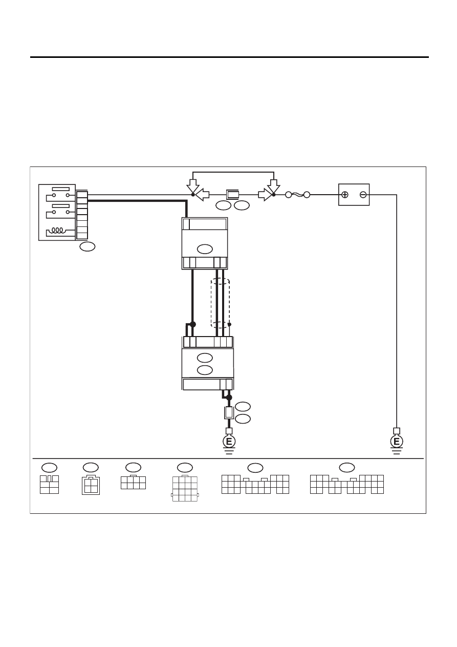
A: DTC P0030 — HO2S HEATER CONTROL CIRCUIT (BANK 1 SENSOR 1) —
• DTC DETECTING CONDITION:
• Two consecutive driving cycles with fault
CAUTION:
After repair or replacement of faulty parts, conduct Clear Memory Mode<Ref. to EN(H4SO)-47, OPER-
ATION, Clear Memory Mode.> and Inspection Mode <Ref. to EN(H4SO)-40, OPERATION, Inspection
Mode.> .
• WIRING DIAGRAM:
EN-01144
F44
B61
6
RHD
RHD
BATTERY
SBF-5
B47
MAIN RELAY
1
2
3
5
4
6
F44
1 2 3 4
5 6 7 8
C16
C5
4
8
B22
E3
ECM
C6
C17
C22
C13
B23
3
2
1
FRONT OXYGEN
(A/F) SENSOR
B18
B135
B:
B136
C:
B22
1 2 3 4
5 6 7 8
9 10 11 12
13 14 15 16
B47
3
4
5
6
1
2
B136
5 6
7
2
1
9
8
4
3
23
21 22
24
10 11 12 13 14
25 26
15 16 17
18 19 20
B18
4
2 1
3
LHD
LHD
5 6 7
8
2
1
9
4
3
10
24
22 23
25
11 12 13 14 15
26
27 28
16 17 18 19
20 21
B135

EN(H4SO)-91
ENGINE (DIAGNOSTICS)
DIAGNOSTIC PROCEDURE WITH DIAGNOSTIC TROUBLE CODE (DTC)
Step
Value
Yes
No
1
CHECK HARNESS BETWEEN ECM AND
FRONT OXYGEN (A/F) SENSOR CONNEC-
TOR.
1) Start and warm-up engine.
2) Turn ignition switch to OFF.
3) Disconnect connectors from ECM and front
oxygen (A/F) sensor.
4) Measure harness resistance between ECM
and front oxygen (A/F) sensor connector.
Connector & terminal
(B136) No. 6 - (B18) No. 3:
(B136) No. 17 - (B18) No. 3:
Is the measured value less than the speci-
fied value?
1 Ω
Repair open circuit
between ECM and
front oxygen (A/F)
sensor connector.
2
CHECK HARNESS BETWEEN ECM AND
FRONT OXYGEN (A/F) SENSOR CONNEC-
TOR.
Measure harness resistance between ECM
and front oxygen (A/F) sensor connector.
Connector & terminal
(B136) No. 13 - (B18) No. 1:
(B136) No. 22 - (B18) No. 2:
Is the measured value less than the specified
value?
1 Ω
Repair open circuit
between ECM and
front oxygen (A/F)
sensor connector.
3
CHECK HARNESS BETWEEN ECM AND
FRONT OXYGEN (A/F) SENSOR CONNEC-
TOR.
Measure harness resistance between main
relay and front oxygen (A/F) sensor connector.
Connector & terminal
(B47) No. 4 — (B18) No. 4:
Is the measured value less than the specified
value?
1
Ω
Repair open circuit
between ECM and
front oxygen (A/F)
sensor connector.
4
CHECK FRONT OXYGEN (A/F) SENSOR.
Measure resistance between terminals in front
oxygen (A/F) sensor connector.
Terminal
No.3 - No.4:
Is the measured value less than the specified
value?
5
Ω
Replace front oxy-
gen (A/F) sensor.
<Ref. to
FU(H4SO)-41,
Front Oxygen (A/
F) Sensor.>
5
CHECK POOR CONTACT.
Check ECM and front oxygen (A/F) sensor
connector for poor contact.
Is there any poor contact in ECM and front
oxygen (A/F) sensor connector.
There is poor contact.
Repair poor con-
tact in ECM and
front oxygen (A/F)
sensor connector.
Replace front oxy-
gen (A/F) sensor.
<Ref. to
FU(H4SO)-41,
Front Oxygen (A/
F) Sensor.>
Нет комментариевНе стесняйтесь поделиться с нами вашим ценным мнением.
Текст