Subaru Legacy III (2000-2003 year). Service manual — part 780
VDC-156
VDC (DIAGNOSTICS)
DIAGNOSTICS CHART WITH SELECT MONITOR
V: DTC 64 NORMAL CLOSING VALVE 1 MALFUNCTION (SECONDARY SUC-
TION VALVE MALFUNCTION)
DIAGNOSIS:
• Faulty harness/connector
• Faulty solenoid valve in VDCH/U
TROUBLE SYMPTOM:
• ABS does not operate.
• VDC does not operate.
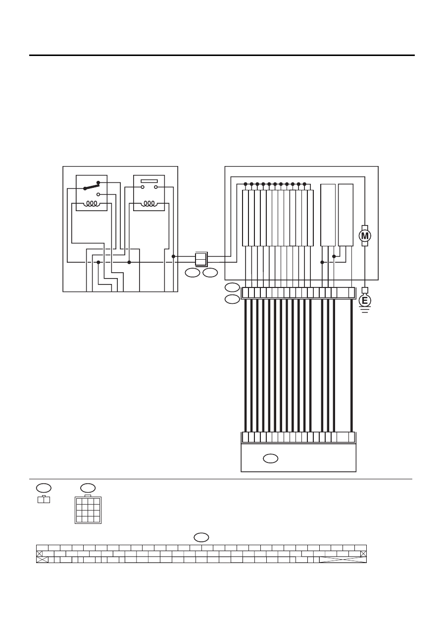
WIRING DIAGRAM:
VDC00142
VDC1
1 2
F91
1
2
3
4
5
6
7
8
9
10
11
12
13
14
15
16
10
9
11
12
15
13
16
14
VDC HYDRAULIC UNIT
VDC5
F91
VDC CONTROL MODULE
F87
FR OUTLET
FR INLET
RL OUTLET
RL INLET
RR OUTLET
RR INLET
PRIMAR
Y CUT
PRIMAR
Y SECTION
SECOND
AR
Y CUT
PRIMAR
Y
PRESSURE SENSOR
SECOND
A
R
Y
PRESSURE SENSOR
SECOND
AR
Y SECTION
FL OUTLET
FL INLET
51
30
3
31
4
23
50
24
25
2
26
36
76
77
78
29
4
5
1
6
2
7
3
8
VDC2
VDC1
1
2
F87
56 57
59 60
62 63
65
82 83
80
27
28
25
26
23
24
21
22
19
20
17
18
15
16
13
14
11
12
9
10
7
8
5
6
3
4
1
2
54
55
52
53
50
51
81
48
49
46
47
44
45
78
79
76
77
75
42
43
40
41
74
72
73
70
71
39
37
38
35
36
69
67
68
66
33
34
61
64
31
32
29
30
58
RELAY BOX
MOTOR RELAY
VALVE RELAY
VDC-157
VDC (DIAGNOSTICS)
DIAGNOSTICS CHART WITH SELECT MONITOR
Step
Value
Yes
No
1
CHECK RESISTANCE OF SOLENOID
VALVE.
1) Turn ignition switch to OFF.
2) Disconnect two connectors (VDC1, F91)
from VDCH/U.
3) Measure resistance between VDCH/U con-
nector terminals.
Connector & terminal
DTC 32/(VDC5) No. 1 — (VDC2) No. 2:
DTC 34/(VDC5) No. 4 — (VDC2) No. 2:
DTC 36/(VDC5) No. 3 — (VDC2) No. 2:
DTC 38/(VDC5) No. 2 — (VDC2) No. 2:
DTC 63/(VDC5) No. 10 — (VDC2) No. 2:
DTC 64/(VDC5) No. 11 — (VDC2) No. 2:
Is the measured value within the specified
range?
3.8 — 4.8
Ω
Replace VDCH/U.
<Ref. to VDC-8,
VDC Control Mod-
ule (VDCCM).>
2
CHECK GROUND SHORT OF SOLENOID
VALVE.
Measure resistance between VDCH/U connec-
tor and chassis ground.
Connector & terminal
DTC 32/(VDC5) No. 1 — Chassis
ground:
DTC 34/(VDC5) No. 4 — Chassis
ground:
DTC 36/(VDC5) No. 3 — Chassis
ground:
DTC 38/(VDC5) No. 2 — Chassis
ground:
DTC 63/(VDC5) No. 10 — Chassis
ground:
DTC 64/(VDC5) No. 11 — Chassis
ground:
Does the measured value exceed the specified
value?
1 M
Ω
Replace VDCH/U.
<Ref. to VDC-8,
VDC Control Mod-
ule (VDCCM).>
3
CHECK BATTERY SHORT OF SOLENOID
VALVE.
1) Disconnect connector from VDCCM.
2) Measure voltage between VDCH/U con-
nector and chassis ground.
Connector & terminal
DTC 32/(VDC5) No. 1 (+) — Chassis
ground (
−−−−
):
DTC 34/(VDC5) No. 4 (+) — Chassis
ground (
−−−−
):
DTC 36/(VDC5) No. 3 (+) — Chassis
ground (
−−−−
):
DTC 38/(VDC5) No. 2 (+) — Chassis
ground (
−−−−
):
DTC 63/(VDC5) No. 10 (+) — Chassis
ground (
−−−−
):
DTC 64/(VDC5) No. 11 (+) — Chassis
ground (
−−−−
):
Is the measured value less than the speci-
fied value?
1 V
Replace VDCH/U.
<Ref. to VDC-8,
VDC Control Mod-
ule (VDCCM).>
VDC-158
VDC (DIAGNOSTICS)
DIAGNOSTICS CHART WITH SELECT MONITOR
4
CHECK BATTERY SHORT OF SOLENOID
VALVE.
1) Turn ignition switch to ON.
2) Measure voltage between VDCH/U con-
nector and chassis ground.
Connector & terminal
DTC 32/(VDC5) No. 1 (+) — Chassis
ground (
−−−−
):
DTC 34/(VDC5) No. 4 (+) — Chassis
ground (
−−−−
):
DTC 36/(VDC5) No. 3 (+) — Chassis
ground (
−−−−
):
DTC 38/(VDC5) No. 2 (+) — Chassis
ground (
−−−−
):
DTC 63/(VDC5) No. 10 (+) — Chassis
ground (
−−−−
):
DTC 64/(VDC5) No. 11 (+) — Chassis
ground (
−−−−
):
Is the measured value less than the speci-
fied value?
1 V
Replace VDCH/U.
<Ref. to VDC-8,
VDC Control Mod-
ule (VDCCM).>
5
CHECK BATTERY SHORT OF HARNESS.
1) Turn ignition switch to OFF.
2) Measure voltage between VDCCM connec-
tor and chassis ground.
Connector & terminal
DTC 32/(F87) No. 3 (+) — Chassis
ground (
−−−−
):
DTC 34/(F87) No. 51 (+) — Chassis
ground (
−−−−
):
DTC 36/(F87) No. 50 (+) — Chassis
ground (
−−−−
):
DTC 38/(F87) No. 4 (+) — Chassis
ground (
−−−−
):
DTC 63/(F87) No. 29 (+) — Chassis
ground (
−−−−
):
DTC 64/(F87) No. 2 (+) — Chassis
ground (
−−−−
):
Is the measured value less than the speci-
fied value?
1 V
Repair harness
between VDCCM
and VDCH/U.
6
CHECK BATTERY SHORT OF HARNESS.
1) Turn ignition switch to ON.
2) Measure voltage between VDCCM connec-
tor and chassis ground.
Connector & terminal
DTC 32/(F87) No. 3 (+) — Chassis
ground (
−−−−
):
DTC 34/(F87) No. 51 (+) — Chassis
ground (
−−−−
):
DTC 36/(F87) No. 50 (+) — Chassis
ground (
−−−−
):
DTC 38/(F87) No. 4 (+) — Chassis
ground (
−−−−
):
DTC 63/(F87) No. 29 (+) — Chassis
ground (
−−−−
):
DTC 64/(F87) No. 2 (+) — Chassis
ground (
−−−−
):
Is the measured value less than the speci-
fied value?
1 V
Repair harness
between VDCCM
and VDCH/U.
Step
Value
Yes
No
VDC-159
VDC (DIAGNOSTICS)
DIAGNOSTICS CHART WITH SELECT MONITOR
7
CHECK GROUND SHORT OF HARNESS.
1) Turn ignition switch to OFF.
2) Measure resistance between VDCCM con-
nector and chassis ground.
Connector & terminal
DTC 32/(F87) No. 3 — Chassis ground:
DTC 34/(F87) No. 51 — Chassis ground:
DTC 36/(F87) No. 50 — Chassis ground:
DTC 38/(F87) No. 4 — Chassis ground:
DTC 63/(F87) No. 29 — Chassis ground:
DTC 64/(F87) No. 2 — Chassis ground:
Does the measured value exceed the spec-
ified value?
1 M
Ω
Repair harness
between VDCCM
and VDCH/U.
8
CHECK HARNESS/CONNECTOR BETWEEN
VDCCM AND VDCH/U.
1) Connect connector (F91) to VDCH/U.
2) Measure resistance between VDCCM con-
nector and VDCH/U connector.
Connector & terminal
DTC 32/(F87) No. 3 — (VDC2) No. 1:
DTC 34/(F87) No. 51 — (VDC2) No. 1:
DTC 36/(F87) No. 50 — (VDC2) No. 1:
DTC 38/(F87) No. 4 — (VDC2) No. 1:
DTC 63/(F87) No. 29 — (VDC2) No. 1:
DTC 64/(F87) No. 2 — (VDC2) No. 1:
Is the measured value within the specified
range?
3 — 6
Ω
Repair harness/
connector
between VDCCM
and VDCH/U.
9
CHECK POOR CONTACT IN CONNECTORS.
Is there poor contact in connectors between
VDCCM and VDCH/U?
Tightened securely.
Repair connector.
10
CHECK VDCCM.
1) Connect all connectors.
2) Erase the memory.
3) Perform inspection mode.
4) Read out the diagnostic trouble code.
Is the same diagnostic trouble code as in
the current diagnosis still being output?
There is poor contact.
Replace VDCCM.
<Ref. to VDC-8,
VDC Control Mod-
ule (VDCCM).>
11
CHECK ANY OTHER DIAGNOSTIC TROU-
BLE CODES APPEARANCE.
Are other diagnostic trouble codes being out-
put?
Same DTC indicated.
Proceed with the
diagnosis corre-
sponding to the
diagnostic trouble
code.
A temporary poor
contact.
Step
Value
Yes
No
Нет комментариевНе стесняйтесь поделиться с нами вашим ценным мнением.
Текст