Subaru Legacy III (2000-2003 year). Service manual — part 778
VDC-148
VDC (DIAGNOSTICS)
DIAGNOSTICS CHART WITH SELECT MONITOR
9
CHECK CONTAMINATION OF ABS SENSOR
OR TONE WHEEL.
Remove disc rotor from hub.
Is the ABS sensor pole piece or the tone wheel
contaminated by dirt or other foreign matter?
Dirt or foreign matter found.
Thoroughly
remove dirt or
other foreign mat-
ter.
10
CHECK DAMAGE OF ABS SENSOR OR
TONE WHEEL.
Are there broken or damaged teeth in the ABS
sensor pole piece or the tone wheel?
Broken or damaged.
Replace ABS sen-
sor or tone wheel.
Front <Ref. to
VDC-27, Front
ABS Sensor.> and
<Ref. to VDC-29,
Front Tone
Wheel.> Rear
<Ref. to VDC-28,
Rear ABS Sen-
sor.> and <Ref. to
VDC-30, Rear
Tone Wheel.>
11
CHECK TONE WHEEL RUNOUT.
Measure tone wheel runout.
Is the measured value less than the specified
value?
0.05 mm (0.0020 in)
Repair tone wheel.
Front <Ref. to
VDC-29, Front
Tone Wheel.>
Rear <Ref. to
VDC-30, Rear
Tone Wheel.>
12
CHECK VDCCM.
1) Turn ignition switch to OFF.
2) Connect all connectors.
3) Erase the memory.
4) Perform inspection mode.
5) Read out the diagnostic trouble code.
Is the same diagnostic trouble code as in
the current diagnosis still being output?
Same pattern.
Replace VDCCM.
<Ref. to VDC-8,
VDC Control Mod-
ule (VDCCM).>
13
CHECK ANY OTHER DIAGNOSTIC TROU-
BLE CODES APPEARANCE.
Are other diagnostic trouble codes being out-
put?
Other DTC indicated.
Proceed with the
diagnosis corre-
sponding to the
diagnostic trouble
code.
A temporary poor
contact.
Step
Value
Yes
No
VDC-149
VDC (DIAGNOSTICS)
DIAGNOSTICS CHART WITH SELECT MONITOR
K: DTC 31 FR HOLD VALVE MALFUNCTION (FRONT RIGHT INLET VALVE
MALFUNCTION)
NOTE:
For diagnostic procedure, refer to DTC 62. <Ref. to VDC-150, DTC 62 NORMAL OPENING VALVE 1 MAL-
FUNCTION (SECONDARY CUT VALVE MALFUNCTION), Diagnostics Chart with Select Monitor.>
L: DTC 33 FL HOLD VALVE MALFUNCTION (FRONT LEFT INLET VALVE MAL-
FUNCTION)
NOTE:
For diagnostic procedure, refer to DTC 62. <Ref. to VDC-150, DTC 62 NORMAL OPENING VALVE 1 MAL-
FUNCTION (SECONDARY CUT VALVE MALFUNCTION), Diagnostics Chart with Select Monitor.>
M: DTC 35 RR HOLD VALVE MALFUNCTION (REAR RIGHT INLET VALVE MAL-
FUNCTION)
NOTE:
For diagnostic procedure, refer to DTC 62. <Ref. to VDC-150, DTC 62 NORMAL OPENING VALVE 1 MAL-
FUNCTION (SECONDARY CUT VALVE MALFUNCTION), Diagnostics Chart with Select Monitor.>
N: DTC 37 RL HOLD VALVE MALFUNCTION (REAR LEFT INLET VALVE MAL-
FUNCTION)
NOTE:
For diagnostic procedure, refer to DTC 62. <Ref. to VDC-150, DTC 62 NORMAL OPENING VALVE 1 MAL-
FUNCTION (SECONDARY CUT VALVE MALFUNCTION), Diagnostics Chart with Select Monitor.>
O: DTC 61 NORMAL OPENING VALVE 2 MALFUNCTION (PRIMARY CUT
VALVE MALFUNCTION)
NOTE:
For diagnostic procedure, refer to DTC 62. <Ref. to VDC-150, DTC 62 NORMAL OPENING VALVE 1 MAL-
FUNCTION (SECONDARY CUT VALVE MALFUNCTION), Diagnostics Chart with Select Monitor.>
VDC-150
VDC (DIAGNOSTICS)
DIAGNOSTICS CHART WITH SELECT MONITOR
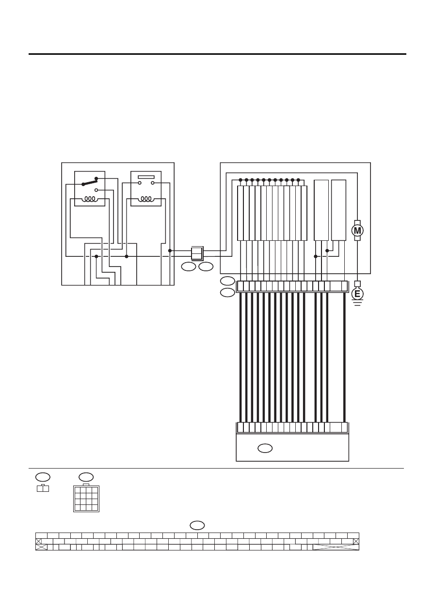
P: DTC 62 NORMAL OPENING VALVE 1 MALFUNCTION (SECONDARY CUT
VALVE MALFUNCTION)
DIAGNOSIS:
• Faulty harness/connector
• Faulty solenoid valve in VDCH/U
TROUBLE SYMPTOM:
• ABS does not operate.
• VDC does not operate.
WIRING DIAGRAM:
VDC00142
VDC1
1 2
F91
1
2
3
4
5
6
7
8
9
10
11
12
13
14
15
16
10
9
11
12
15
13
16
14
VDC HYDRAULIC UNIT
VDC5
F91
VDC CONTROL MODULE
F87
FR OUTLET
FR INLET
RL OUTLET
RL INLET
RR OUTLET
RR INLET
PRIMAR
Y CUT
PRIMAR
Y SECTION
SECOND
AR
Y CUT
PRIMAR
Y
PRESSURE SENSOR
SECOND
A
R
Y
PRESSURE SENSOR
SECOND
AR
Y SECTION
FL OUTLET
FL INLET
51
30
3
31
4
23
50
24
25
2
26
36
76
77
78
29
4
5
1
6
2
7
3
8
VDC2
VDC1
1
2
F87
56 57
59 60
62 63
65
82 83
80
27
28
25
26
23
24
21
22
19
20
17
18
15
16
13
14
11
12
9
10
7
8
5
6
3
4
1
2
54
55
52
53
50
51
81
48
49
46
47
44
45
78
79
76
77
75
42
43
40
41
74
72
73
70
71
39
37
38
35
36
69
67
68
66
33
34
61
64
31
32
29
30
58
RELAY BOX
MOTOR RELAY
VALVE RELAY
VDC-151
VDC (DIAGNOSTICS)
DIAGNOSTICS CHART WITH SELECT MONITOR
Step
Value
Yes
No
1
CHECK RESISTANCE OF SOLENOID
VALVE.
1) Turn ignition switch to OFF.
2) Disconnect two connectors (VDC1, F91)
from VDCH/U.
3) Measure resistance between VDCH/U con-
nector terminals.
Connector & terminal
DTC 31/(VDC5) No. 5 — (VDC2) No. 2:
DTC 33/(VDC5) No. 8 — (VDC2) No. 2:
DTC 35/(VDC5) No. 7 — (VDC2) No. 2:
DTC 37/(VDC5) No. 6 — (VDC2) No. 2:
DTC 61/(VDC5) No. 9 — (VDC2) No. 2:
DTC 62/(VDC5) No. 12 — (VDC2) No. 2:
Is the measured value within the specified
range?
8.04 — 9.04
Ω
Replace VDCH/U.
<Ref. to VDC-8,
VDC Control Mod-
ule (VDCCM).>
2
CHECK GROUND SHORT OF SOLENOID
VALVE.
Measure resistance between VDCH/U connec-
tor and chassis ground.
Connector & terminal
DTC 31/(VDC5) No. 5 — Chassis
ground:
DTC 33/(VDC5) No. 8 — Chassis
ground:
DTC 35/(VDC5) No. 7 — Chassis
ground:
DTC 37/(VDC5) No. 6 — Chassis
ground:
DTC 61/(VDC5) No. 9 — Chassis
ground:
DTC 62/(VDC5) No. 12 — Chassis
ground:
Does the measured value exceed the specified
value?
1 M
Ω
Replace VDCH/U.
<Ref. to VDC-8,
VDC Control Mod-
ule (VDCCM).>
3
CHECK BATTERY SHORT OF SOLENOID
VALVE.
1) Disconnect connector from VDCCM.
2) Measure voltage between VDCH/U con-
nector and chassis ground.
Connector & terminal
DTC 31/(VDC5) No. 5 (+) — Chassis
ground (
−−−−
):
DTC 33/(VDC5) No. 8 (+) — Chassis
ground (
−−−−
):
DTC 35/(VDC5) No. 7 (+) — Chassis
ground (
−−−−
):
DTC 37/(VDC5) No. 6 (+) — Chassis
ground (
−−−−
):
DTC 61/(VDC5) No. 9 (+) — Chassis
ground (
−−−−
):
DTC 62/(VDC5) No. 12 (+) — Chassis
ground (
−−−−
):
Is the measured value less than the speci-
fied value?
1 V
Replace VDCH/U.
<Ref. to VDC-8,
VDC Control Mod-
ule (VDCCM).>
Нет комментариевНе стесняйтесь поделиться с нами вашим ценным мнением.
Текст