Subaru Legacy III (2000-2003 year). Service manual — part 807
VDC-264
VDC (DIAGNOSTICS)
DIAGNOSTICS CHART WITH SELECT MONITOR
7
CHECK GROUND SHORT OF HARNESS.
1) Turn ignition switch to OFF.
2) Disconnect connector from VDCCM.
3) Measure resistance between VDCH/U con-
nector and chassis ground.
Connector & terminal
(F91) No. 13 — Chassis ground:
Does the measured value exceed the spec-
ified value?
1 M
Ω
Repair harness
between VDCH/U
and VDCCM.
8
CHECK BATTERY SHORT OF HARNESS.
Measure voltage between VDCH/U connector
and chassis ground.
Connector & terminal
(F91) No. 13 (+) — Chassis ground (
−−−−
):
Is the measured value less than the specified
value?
0.5 V
Repair harness
between VDCH/U
and VDCCM.
9
CHECK BATTERY SHORT OF HARNESS.
1) Turn ignition switch to ON.
2) Measure voltage between VDCH/U con-
nector and chassis ground.
Connector & terminal
(F91) No. 13 (+) — Chassis ground (
−−−−
):
Is the measured value less than the speci-
fied value?
0.5 V
Repair harness
between VDCH/U
and VDCCM.
10
CHECK INPUT VOLTAGE OF PRESSURE
SENSOR.
1) Turn ignition switch to OFF.
2) Disconnect connector from VDCCM.
3) Remove cover from VDCCM. <Ref. to
VDC-19, REMOVE, VDCCM Connector
Cover.>
4) Connect connector to VDCCM.
5) Connect all connectors.
6) Turn ignition switch to ON.
7) Do not depress brake pedal.
8) Measure voltage between VDCCM connec-
tor terminals.
Connector & terminal
(F87) No. 77 (+) — No. 76 (
−−−−
):
Is the measured value within the specified
range?
0.48 — 0.72 V
Replace VDCH/U.
<Ref. to VDC-8,
VDC Control Mod-
ule (VDCCM).>
11
CHECK POOR CONTACT IN CONNECTORS.
Is there poor contact in connector between
VDCCM and pressure sensor?
There is poor contact.
Repair connector.
12
CHECK VDCCM.
1) Connect all connectors.
2) Erase the memory.
3) Perform inspection mode.
4) Read out the diagnostic trouble code.
Is the same diagnostic trouble code as in
the current diagnosis still being output?
Same DTC indicated.
Replace VDCCM.
<Ref. to VDC-8,
VDC Control Mod-
ule (VDCCM).>
13
CHECK ANY OTHER DIAGNOSTIC TROU-
BLE CODES APPEARANCE.
Are other diagnostic trouble codes being out-
put?
Other DTC indicated.
Proceed with the
diagnosis corre-
sponding to the
diagnostic trouble
code.
A temporary poor
contact.
Step
Value
Yes
No
VDC-265
VDC (DIAGNOSTICS)
DIAGNOSTICS CHART WITH SELECT MONITOR
MEMO:
VDC-266
VDC (DIAGNOSTICS)
DIAGNOSTICS CHART WITH SELECT MONITOR
BD:DTC 74 VOLTAGE INPUTTED TO PRESSURE SENSOR 2 EXCEEDS SPECI-
FICATION. (SECONDARY PRESSURE SENSOR)
DIAGNOSIS:
• Faulty secondary pressure sensor
TROUBLE SYMPTOM:
• ABS does not operate.
• VDC does not operate.
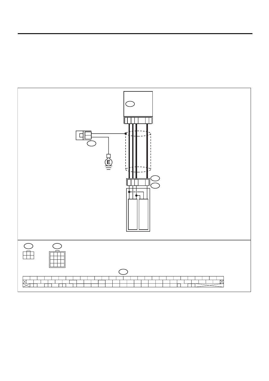
WIRING DIAGRAM:
VDC00181
78
36
77
76
F91
VDC5
F88
2
3
F88
F91
F87
56 57
59 60
62 63
65
82 83
80
27
28
25
26
23
24
21
22
19
20
17
18
15
16
13
14
11
12
9
10
7
8
5
6
3
4
1
2
54
55
52
53
50
51
81
48
49
46
47
44
45
78
79
76
77
75
42
43
40
41
74
72
73
70
71
39
37
38
35
36
69
67
68
66
33
34
61
64
31
32
29
30
58
VDC HYDRAULIC
UNIT
PRIMAR
Y
PRESSURE SENSOR
SECOND
AR
Y
PRESSURE SENSOR
15
13
16
14
1
2
3
4
5
6
7
8
9
10
11
12
13
14
15
16
F87
VDC
CONTROL
MODULE
1
3
4 5 6
2
VDC-267
VDC (DIAGNOSTICS)
DIAGNOSTICS CHART WITH SELECT MONITOR
Step
Value
Yes
No
1
CHECK GROUND CIRCUIT OF PRESSURE
SENSOR.
1) Turn ignition switch to OFF.
2) Disconnect connector (F91) from VDCH/U.
3) Measure resistance between VDCH/U con-
nector and chassis ground.
Connector & terminal
(F91) No. 15 — Chassis ground:
Is the measured value less than the speci-
fied value?
0.5
Ω
2
CHECK GROUND CIRCUIT OF VDCCM.
1) Disconnect connector from VDCCM.
2) Remove cover from VDCCM. <Ref. to
VDC-19, REMOVE, VDCCM Connector
Cover.>
3) Connect connector to VDCCM.
4) Measure resistance between VDCCM and
chassis ground.
Connector & terminal
(F87) No. 76 — Chassis ground:
Is the measured value less than the speci-
fied value?
0.5
Ω
Replace harness
between VDCH/U
and VDCCM.
3
CHECK POOR CONTACT IN CONNECTORS.
Is there poor contact in VDCCM connector?
There is poor contact.
Repair or replace
VDCCM connec-
tor.
Replace VDCCM.
<Ref. to VDC-8,
VDC Control Mod-
ule (VDCCM).>
4
CHECK POWER SUPPLY OF PRESSURE
SENSOR.
NOTE:
When this inspection is carried out, DTC 51 AB-
NORMAL VALVE RELAY is memorized, but
this does not indicate valve relay malfunction.
1) Turn ignition switch to ON.
2) Measure voltage between VDCH/U con-
nector terminals.
Connector & terminal
(F91) No. 16 (+) — No. 15 (
−−−−
):
Is the measured value within the specified
range?
4.75 — 5.25 V
5
CHECK POWER SUPPLY OF VDCCM.
1) Turn ignition switch to OFF.
2) Disconnect connector from VDCCM.
3) Remove cover from VDCCM. <Ref. to
VDC-19, VDCCM Connector Cover.>
4) Connect connector to VDCCM.
5) Turn ignition switch to ON.
6) Measure voltage between VDCCM connec-
tor terminals.
Connector & terminal
(F87) No. 78 (+) — No. 76 (
−−−−
):
Is the measured value within the specified
range?
4.75 — 5.25 V
Repair harness
between VDCH/U
and VDCCM.
6
CHECK POOR CONTACT IN CONNECTORS.
Is there poor contact in VDCCM connector?
There is poor contact.
Repair or replace
VDCCM connec-
tor.
Replace VDCCM.
<Ref. to VDC-8,
VDC Control Mod-
ule (VDCCM).>
Нет комментариевНе стесняйтесь поделиться с нами вашим ценным мнением.
Текст