Subaru Legacy III (2000-2003 year). Service manual — part 805
VDC-256
VDC (DIAGNOSTICS)
DIAGNOSTICS CHART WITH SELECT MONITOR
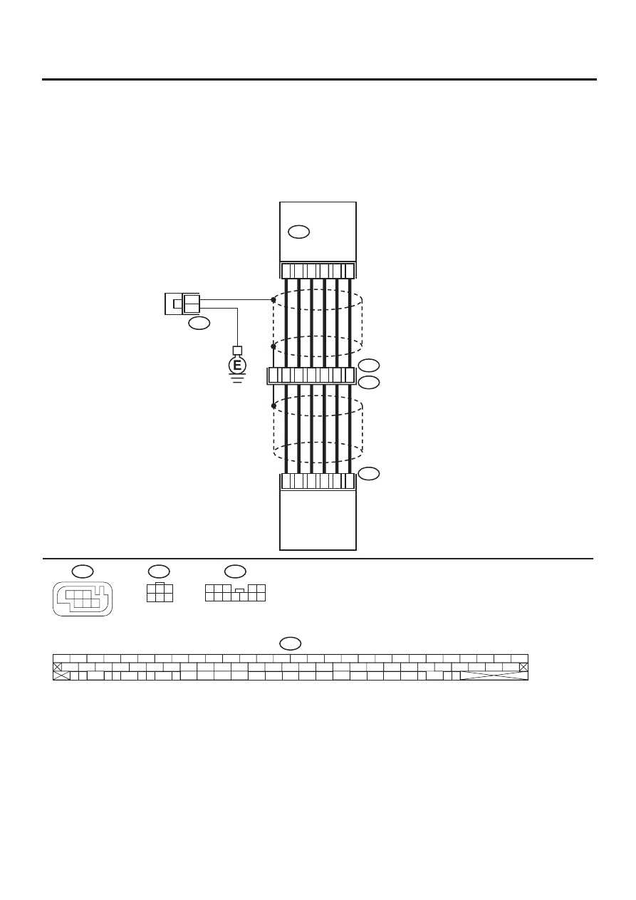
BA:DTC 73 EXCESSIVE LATERAL G SENSOR SIGNAL
DIAGNOSIS:
• Faulty lateral G sensor
TROUBLE SYMPTOM:
• ABS does not operate.
• VDC does not operate.
WIRING DIAGRAM:
VDC00182
65
63
67
66
70
64
10
11
9
F88
F55
R49
4
3
12
2
4
5
8
1
5
6
R100
6
F88
R100
F55
F87
56 57
59 60
62 63
65
82 83
80
27
28
25
26
23
24
21
22
19
20
17
18
15
16
13
14
11
12
9
10
7
8
5
6
3
4
1
2
54
55
52
53
50
51
81
48
49
46
47
44
45
78
79
76
77
75
42
43
40
41
74
72
73
70
71
39
37
38
35
36
69
67
68
66
33
34
61
64
31
32
29
30
58
F87
VDC
CONTROL
MODULE
YAW RATE
AND LATERAL G
SENSOR
1
3
4 5 6
2
1 2 3
4 5
6 7 8 9 10 11 12
3
1
3
4 5 6
2

VDC-257
VDC (DIAGNOSTICS)
DIAGNOSTICS CHART WITH SELECT MONITOR
Step
Value
Yes
No
1
CHECK INSTALLATION OF YAW RATE AND
LATERAL G SENSOR.
Check installation of yaw rate and lateral G
sensor.
Is the yaw rate and lateral G sensor fixed
securely?
Fixed securely.
Install yaw rate
and lateral G sen-
sor securely.
2
CHECK OUTPUT OF LATERAL G SENSOR
USING SELECT MONITOR.
1) Stop the vehicle on a flat road.
2) Select “Current data display & Save” on the
select monitor.
3) Read yaw rate and lateral G sensor output
on the select monitor display.
Is the measured value within the specified
range?
2.3 — 2.7 V
Replace yaw rate
and lateral G sen-
sor. <Ref. to VDC-
22, Yaw Rate and
Lateral G Sensor.>
3
CHECK POOR CONTACT IN CONNECTORS.
Turn ignition switch to OFF.
Is there poor contact in connector between
VDCCM and yaw rate and lateral G sensor?
There is poor contact.
Repair connector.
4
CHECK VDCCM.
1) Connect all connectors.
2) Erase the memory.
3) Perform inspection mode.
4) Read out the diagnostic trouble code.
Is the same diagnostic trouble code as in
the current diagnosis still being output?
Same DTC indicated.
Replace VDCCM.
<Ref. to VDC-8,
VDC Control Mod-
ule (VDCCM).>
5
CHECK ANY OTHER DIAGNOSTIC TROU-
BLE CODES APPEARANCE.
Are other diagnostic trouble codes being out-
put?
Other DTC indicated.
Proceed with the
diagnosis corre-
sponding to the
diagnostic trouble
code.
A temporary poor
contact.
VDC-258
VDC (DIAGNOSTICS)
DIAGNOSTICS CHART WITH SELECT MONITOR
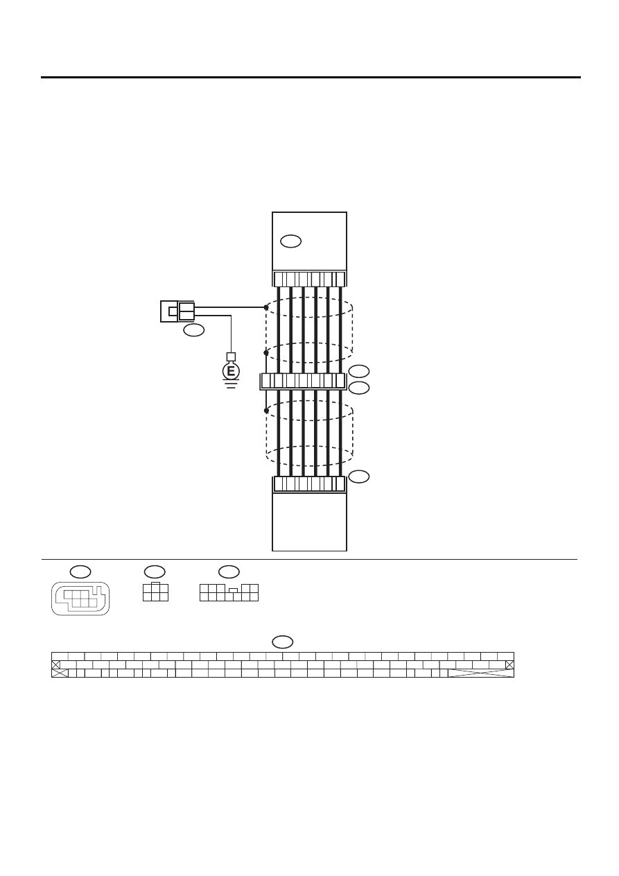
BB:DTC 73 VOLTAGE INPUTTED TO LATERAL G SENSOR EXCEEDS SPECIFI-
CATION.
DIAGNOSIS:
• Faulty lateral G sensor
TROUBLE SYMPTOM:
• ABS does not operate.
• VDC does not operate.
WIRING DIAGRAM:
VDC00182
65
63
67
66
70
64
10
11
9
F88
F55
R49
4
3
12
2
4
5
8
1
5
6
R100
6
F88
R100
F55
F87
56 57
59 60
62 63
65
82 83
80
27
28
25
26
23
24
21
22
19
20
17
18
15
16
13
14
11
12
9
10
7
8
5
6
3
4
1
2
54
55
52
53
50
51
81
48
49
46
47
44
45
78
79
76
77
75
42
43
40
41
74
72
73
70
71
39
37
38
35
36
69
67
68
66
33
34
61
64
31
32
29
30
58
F87
VDC
CONTROL
MODULE
YAW RATE
AND LATERAL G
SENSOR
1
3
4 5 6
2
1 2 3
4 5
6 7 8 9 10 11 12
3
1
3
4 5 6
2

VDC-259
VDC (DIAGNOSTICS)
DIAGNOSTICS CHART WITH SELECT MONITOR
Step
Value
Yes
No
1
CHECK OUTPUT OF YAW RATE AND LAT-
ERAL G SENSOR USING SELECT MONI-
TOR.
1) Stop the vehicle on a flat road.
2) Select “Current data display & Save” on the
select monitor.
3) Read yaw rate and lateral G sensor output
on the select monitor display.
Is the measured value within the specified
range?
2.3 — 2.7 V
2
CHECK POOR CONTACT IN CONNECTORS.
Turn ignition switch to OFF.
Is there poor contact in connector between
VDCCM and yaw rate and lateral G sensor?
There is poor contact.
Repair connector.
3
CHECK VDCCM.
1) Connect all connectors.
2) Erase the memory.
3) Perform inspection mode.
4) Read out the diagnostic trouble code.
Is the same diagnostic trouble code as in
the current diagnosis still being output?
Same DTC indicated.
Replace VDCCM.
<Ref. to VDC-8,
VDC Control Mod-
ule (VDCCM).>
4
CHECK ANY OTHER DIAGNOSTIC TROU-
BLE CODES APPEARANCE.
Are other diagnostic trouble codes being out-
put?
Other DTC indicated.
Proceed with the
diagnosis corre-
sponding to the
diagnostic trouble
code.
A temporary poor
contact.
5
CHECK INPUT VOLTAGE OF YAW RATE
AND LATERAL G SENSOR.
1) Turn ignition switch to OFF.
2) Remove console box.
3) Disconnect connector from yaw rate and
lateral G sensor.
4) Turn ignition switch to ON.
5) Measure voltage between yaw rate and lat-
eral G sensor connector terminals.
Connector & terminal
(R100) No. 3 (+) — No. 6 (
−−−−
):
Is the measured value within the specified
range?
10 — 15 V
Repair harness/
connector
between yaw rate
and lateral G sen-
sor and VDCCM.
6
CHECK YAW RATE AND LATERAL G SEN-
SOR.
1) Turn ignition switch to OFF.
2) Measure resistance between yaw rate and
lateral G sensor terminals.
Terminals
No. 3 — No. 5:
Is the measured value within the specified
range?
4.3 — 4.9 k
Ω
Replace yaw rate
and lateral G sen-
sor. <Ref. to VDC-
22, Yaw Rate and
Lateral G Sensor.>
Нет комментариевНе стесняйтесь поделиться с нами вашим ценным мнением.
Текст