Subaru Legacy III (2000-2003 year). Service manual — part 841
PS-52
POWER ASSISTED SYSTEM (POWER STEERING)
STEERING GEARBOX [RHD MODEL]
B: INSTALLATION
1) Insert gearbox into crossmember, being careful
not to damage gearbox boot.
2) Tighten gearbox to crossmember bracket via
clamp with bolt to the specified torque.
Tightening torque:
59 N·m (6.0 kgf-m, 43 ft-lb)
3) Connect pipes C and D to control valve of gear
box assembly.
Tightening torque:
15 N·m (1.5 kgf-m, 10.8 ft-lb)
4) Install universal joint. <Ref. to PS-25, INSTAL-
LATION, Universal Joint.>
5) Connect tie-rod end and knuckle arm, and tight-
en with castle nut. Fit cotter pin into the nut and
bend the pin to lock.
Castle nut tightening torque:
Tighten to 27.0 N·m (2.75 kgf-m, 19.9 ft-lb),
and tighten further within 60
°°°°
until cotter
pin hole is aligned with a slot in the nut.
CAUTION:
When connecting, do not hit cap at the bottom
of tie-rod end with hammer.
6) Install front stabilizer to vehicle.
7) Install front exhaust pipe assembly.
8) Lower the vehicle.
9) Align center of roll connector. <Ref. to AB-19,
ADJUSTMENT, Roll Connector.>
CAUTION:
Ensure that front wheels are set in straight for-
ward direction.
10) Install steering wheel. <Ref. to PS-24, INSTAL-
LATION, Steering Wheel.>
11) Install tires.
12) Tighten wheel nuts to the specified torque.
Tightening torque:
88 N·m (9.0 kgf-m, 65 ft-lb)
13) Connect connector to O
2
sensor. (if equipped)
14) Connect ground cable to battery.
15) Pour fluid into oil tank, and bleed air.
<Ref. to PS-92, Power Steering Fluid.>
16) Install air intake duct.
17) Lift-up the vehicle.
18) Check for fluid leaks.
19) Install jack-up plate.
20) Lower vehicle.
21) Check fluid level in oil tank.
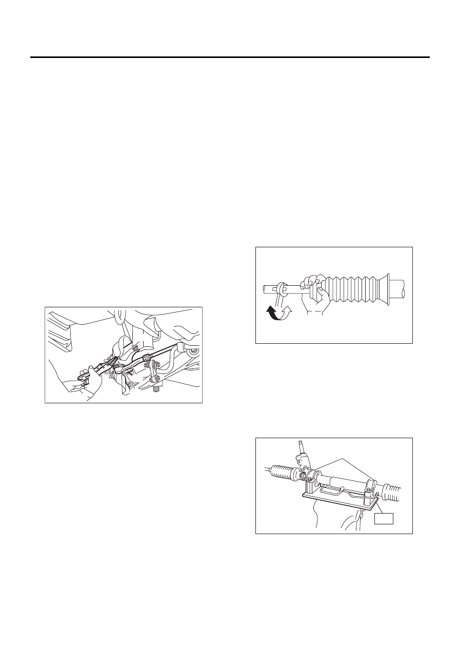
22) After adjusting toe-in and steering angle, tight-
en lock nut on tie-rod end.
Tightening torque:
83 N·m (8.5 kgf-m, 61.5 ft-lb)
CAUTION:
When adjusting toe-in, hold boot as shown to
prevent it from being rotated or twisted. If twist-
ed, straighten it.
C: DISASSEMBLY
1) Secure gearbox removed from vehicle in vise
using ST.
ST
926200000
STAND
CAUTION:
Secure the gearbox assembly in a vise using
the ST as shown. Do not attempt to secure it
without this ST.
(1) Castle nut
(2) Tie-rod end
(3) Knuckle arm
PS-00043
( 1 )
( 2 )
( 3 )
(1) Clamp
PS-00051
PS-00289
( 1 )
ST
PS-53
POWER ASSISTED SYSTEM (POWER STEERING)
STEERING GEARBOX [RHD MODEL]
2) Pry off clip from outer end of boot, and slide boot
toward tie-rod end.
3) Using standard screwdriver, remove band from
boot.
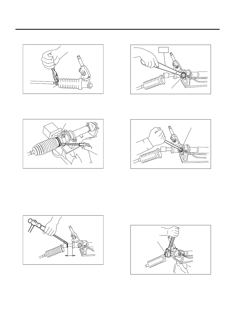
4) Extend rack approximately 40 mm (1.57 in) out.
Unlock lock wire at lock washer on each side of tie-
rod end using a standard screwdriver.
CAUTION:
Be careful not to scratch rack surface as oil
leaks may result.
5) Using ST, loosen lock nut.
ST
926230000
SPANNER
6) Tighten adjusting screw until it no longer tight-
ens.
7) Using a wrench (32 mm width across flats) or ad-
justable wrench, remove tie-rod.
CAUTION:
• Check ball joint for free play, and tie-rod for
bends. Replace if necessary.
• Check dust seals used with tie-rod end ball
joint for damage or deterioration. Replace if
necessary.
(1) Clip
(1) Band
PS-00290
( 1 )
PS-00291
( 1 )
PS-00292
40 mm (1.57 in)
(1) Lock nut
(1) Adjusting screw
(1) Tie-rod
PS-00293
( 1 )
ST
PS-00294
( 1 )
PS-00295
( 1 )
PS-54
POWER ASSISTED SYSTEM (POWER STEERING)
STEERING GEARBOX [RHD MODEL]
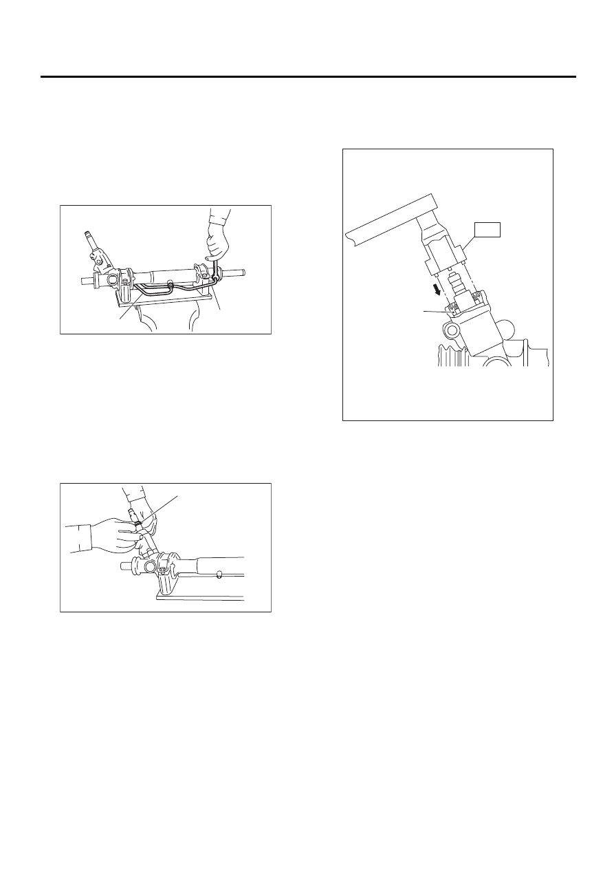
8) Loosen adjusting screw and remove spring and
sleeve.
CAUTION:
Replace spring and/or sleeve if damaged.
9) Disconnect pipes A and B from steering body
and control valve housing.
CAUTION:
Replace pipes and/or flare nuts if damaged.
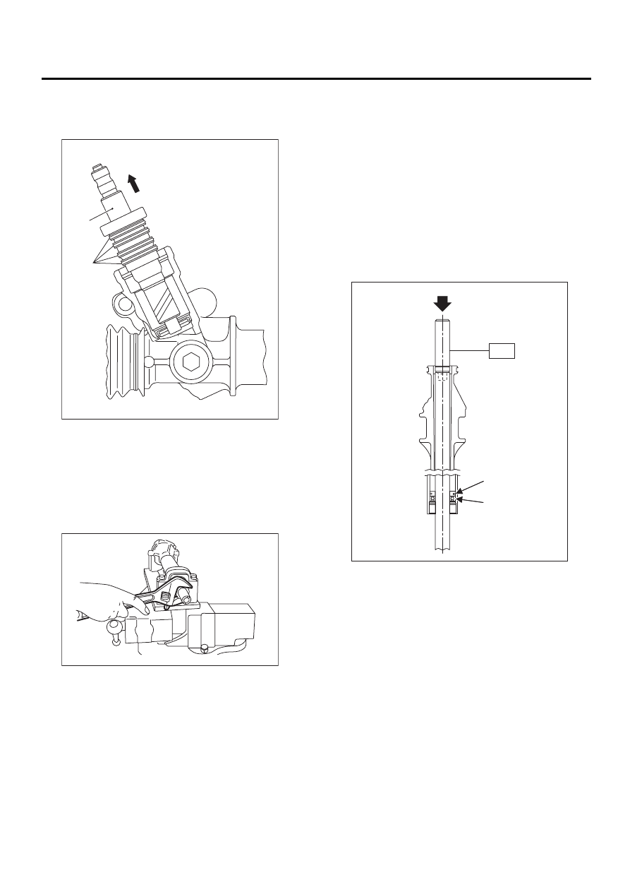
10) Slide dust cover out.
CAUTION:
• Be careful not to scratch housing or input
shaft during dust cover removal. Also do not al-
low foreign matter to enter housing interior.
• Replace dust cover with a new one if its in-
side bore or lips are worn or damaged.
11) Using ST, remove plug.
ST
34199AE090
PLUG WRENCH
NOTE:
Make sure to align ST pin to plug hole.
(1) Pipe A
(2) Pipe B
(1) Dust cover
PS-00296
( 1 )
( 2 )
PS-00297
( 1 )
(1) Plug
PS-00298
( 1 )
ST
PS-55
POWER ASSISTED SYSTEM (POWER STEERING)
STEERING GEARBOX [RHD MODEL]
12) Remove valve assembly.
CAUTION:
Be careful not to scratch seal ring.
13) Remove holder using a 32 mm wrench or ad-
justable wrench.
CAUTION:
Discard old holder and replace with new one.
14) Install ST on valve side of rack and press outer
side oil seal out.
ST 34099FA030 INSTALLER
&
REMOVER
CAUTION:
• Block pipe connection of steering body to
prevent fluid from flowing out.
• Do not allow rack to come in contact with in-
ner wall of cylinder. Otherwise, cylinder wall
may be scratched, resulting in oil leaks.
• Remove holder and rack as a unit.
• Check rack and steering body for bends or
cracks; replace as required.
• Discard oil seal after removal and replace
with new ones.
(1) Valve ASSY
(2) Seal ring
PS-00299
( 1 )
( 2 )
PS-00300
(1) Rack piston
(2) Outer side oil seal
PS-00301
ST
( 1 )
( 2 )
Нет комментариевНе стесняйтесь поделиться с нами вашим ценным мнением.
Текст