Subaru Legacy III (2000-2003 year). Service manual — part 750
VDC-36
VDC (DIAGNOSTICS)
DIAGNOSTICS CHART WITH DIAGNOSIS CONNECTOR
Step
Value
Yes
No
1
CHECK IF OTHER WARNING LIGHTS TURN
ON.
Turn ignition switch to ON (engine OFF).
Do other warning lights turn on?
Warning lights turn on.
Repair combina-
tion meter. <Ref.
to IDI-14, Combi-
nation Meter
Assembly.>
2
CHECK LIGHT BULB.
1) Turn ignition switch to OFF.
2) Remove combination meter.
3) Remove ABS warning light bulb, VDC
warning light bulb, VDC operating indicator
light bulb or VDC OFF indicator light bulb
from combination meter.
Is light bulb OK?
OK.
Replace faulty
light bulb. <Ref. to
IDI-15, DISAS-
SEMBLY, Combi-
nation Meter
Assembly.>
3
CHECK BATTERY SHORT OF LIGHT HAR-
NESS.
1) Disconnect VDCCM connector from
VDCCM.
2) Place a sheet of thick paper [thickness 1.5
mm (0.059 in)] in switch area of VDCCM
connector.
3) Turn ignition switch to ON.
4) Measure voltage between VDC connector
and chassis ground.
Connector & terminal
ABS warning light
(F87) No. 54 (+) — Chassis ground (
−−−−
):
VDC warning light
(F87) No. 53 (+) — Chassis ground (
−−−−
):
VDC operating indicator light
(F87) No. 32 (+) — Chassis ground (
−−−−
):
VDC OFF indicator light
(F87) No. 52 (+) — Chassis ground (
−−−−
):
Does the measured value exceed the spec-
ified value?
3 V
Repair light har-
ness.
4
CHECK WIRING HARNESS.
1) Turn ignition switch to OFF.
2) Install ABS warning light bulb from combi-
nation meter.
3) Install combination meter.
4) Place a sheet of thick paper [thickness 1.5
mm (0.059 in)] in switch area of VDCCM
connector.
5) Turn ignition switch to ON.
6) Measure voltage between VDCCM connec-
tor and chassis ground.
Connector & terminal
ABS warning light
(F87) No. 54 (+) — Chassis ground (
−−−−
):
VDC warning light
(F87) No. 53 (+) — Chassis ground (
−−−−
):
VDC operating indicator light
(F87) No. 32 (+) — Chassis ground (
−−−−
):
VDC OFF indicator light
(F87) No. 52 (+) — Chassis ground (
−−−−
):
Is the measured value within the specified
range?
10 — 15 V
Repair wiring har-
ness.
5
CHECK POOR CONTACT IN CONNECTORS.
Turn ignition switch to OFF.
Is there poor contact in connectors between
combination meter and VDCCM?
There is poor contact.
Repair connector.

VDC-37
VDC (DIAGNOSTICS)
DIAGNOSTICS CHART WITH DIAGNOSIS CONNECTOR
6
CHECK WARNING AND INDICATOR
LIGHTS.
1) Connect connector to VDCCM.
2) Turn ignition switch to ON.
Do ABS warning light, VDC warning light,
VDC operating indicator light and VDC OFF
indicator light turn on?
Turn(s) on.
A temporary poor
contact.
Replace VDCCM.
<Ref. to VDC-8,
VDC Control Mod-
ule (VDCCM).>
Step
Value
Yes
No
VDC-38
VDC (DIAGNOSTICS)
DIAGNOSTICS CHART WITH DIAGNOSIS CONNECTOR
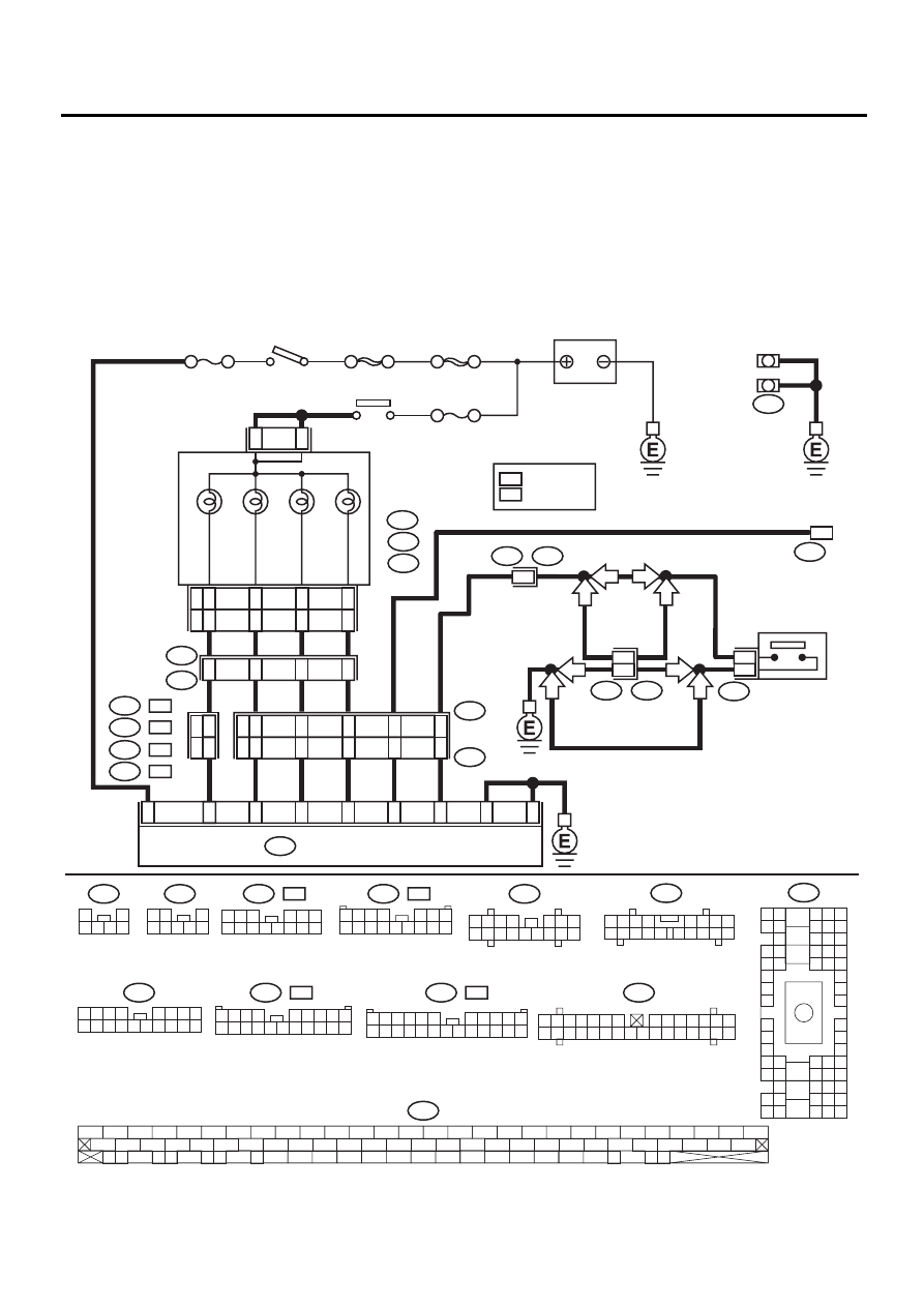
B: ABS AND VDC WARNING LIGHTS DO NOT GO OFF.
DIAGNOSIS:
• ABS warning light circuit is open or shorted.
• VDC warning light circuit is open or shorted.
• Diagnosis circuit is open.
TROUBLE SYMPTOM:
• When starting the engine and while ABS and/or VDC warning light is kept ON.
WIRING DIAGRAM:
• 3.0 L model
VDC00173
NO. 18 15A
SBF-4
DIAGNOSIS
TERMINAL
b5
a8
c7
L
b9
b3
c9
VDC W
ARNING
LIGHT
VDC
OPERA
TING
b2
R
c10
c6
b1
VDC OFF
ABS
W
ARNING
G1
E1
F1
H1
18
12
11
13
20
5
R
L
13
R
L
14
7
4
16
10
54
32
52
53
13
40
55
1
28
SBF-1 100A
NO. 5 15A
8
DIAGNOSIS
CONNECTOR
VDC OFF
SWITCH
VDC CONTROL MODULE
i1
B36
B81
B82
F87
i10
1 2 3 4 5 6 7
8 9 10 11 12 13 14
15 16 17 18 19 20 21 22 23 24 25 26 27 28 29 30
B82
1 2
3
4 5 6 7 8
F87
56 57
59 60
62 63
65
82 83
80
27
28
25
26
23
24
21
22
19
20
17
18
15
16
13
14
11
12
9
10
7
8
5
6
3
4
1
2
54
55
52
53
50
51
81
48
49
46
47
44
45
78
79
76
77
75
42
43
40
41
74
72
73
70
71
39
37
38
35
36
69
67
68
66
33
34
61
64
31
32
29
30
58
B36
B4 B5 B6
A4 A5 A6
C5 C6
F6
D4 D5 D6
F1
H1
C4
G6
G1
C2
K1
M1 M2
K6
L1
D1 D2
A1 A2
B1 B2
I6
J6
L2
I1
J1
H6
M4 M5 M6
L4 L5 L6
N5 N6
O4 O5 O6
N4
P4 P5
N2
O1 O2
P1 P2
N3
O3
P3
P6
A3
B3
C3
E4 E5 E6
E1 E2
i10
a:
i11
b:
i12
B255
F96
c:
COMBINATION
METER
BATTERY
IGNITION
SWITCH
IGNITION
RELAY
i62
i61
i60
i1
B36
: LHD MODEL
: RHD MODEL
L
R
3
5
6
16
J1
i62
1
2
3 4 5 6
i12
1 2 3
8
9 10
4
11 12 13
14 15 16
5 6 7
17 18
i11
1 2 3
8 9 10
4
11 12 13 14 15 16
5 6 7
RHD
RHD
LHD
LHD
RHD
LHD
LHD
RHD
B62
L
:
B100
R
:
F45
L
:
F2
R
:
F2
i60
R
:
F96
R
:
F45
L
:
F96
L
:
1 2 3 4
5 6 7
8 9 10 11 12 13 14 15 16
3 4
1 2
8 9 10 11
12 13 14 15 16 17 18 19 20 21 22 23 24
5 6
7
1 2 3
4 5 6
7 8 9 10 11 12 13 14
1 2 3
8
9 10
4
11 12 13 14 15 16
5 6 7
17 18
1 2 3 4
5 6 7 8 9
10 11 12 13 14 15 16 17 18 19 20
VDC-39
VDC (DIAGNOSTICS)
DIAGNOSTICS CHART WITH DIAGNOSIS CONNECTOR
Step
Value
Yes
No
1
CHECK INSTALLATION OF VDCCM CON-
NECTOR.
Turn ignition switch to OFF.
Is VDCCM connector inserted into VDCCM
until the clamp locks onto it?
VDCCM connector is con-
nected and the clamp is
locked.
Insert VDCCM
connector into
VDCCM until the
clamp locks onto
it.
2
CHECK DIAGNOSIS TERMINAL.
Measure resistance between diagnosis termi-
nals (B81) and chassis ground.
Terminals
Diagnosis terminal (A) — Chassis
ground:
Diagnosis terminal (B) — Chassis
ground:
Is the measured value less than the specified
value?
0.5
Ω
Repair diagnosis
terminal harness.
3
CHECK DIAGNOSIS LINE.
1) Turn ignition switch to OFF.
2) Connect diagnosis terminal (B81) to diag-
nosis connector (B82) No. 8.
3) Disconnect connector from VDCCM.
4) Measure resistance between VDCCM con-
nector and chassis ground.
Connector & terminal
(F87) No. 13 — Chassis ground:
Is the measured value less than the speci-
fied value?
0.5
Ω
Repair harness
connector
between VDCCM
and diagnosis con-
nector.
4
CHECK WIRING HARNESS.
1) Place a sheet of thick paper [thickness 1.5
mm (0.059 in)] in switch area of VDCCM
connector.
2) Turn ignition switch to ON.
Do the ABS warning light and VDC warning
light remain off?
Warning lights remain off.
Repair front wiring
harness.
5
CHECK VDCCM TERMINAL.
1) Turn ignition switch to OFF.
2) Check, if there is any faulty condition of
VDCCM terminal.
Is there any faulty condition of VDCCM ter-
minal?
There is no problem.
Replace VDCCM.
<Ref. to VDC-8,
VDC Control Mod-
ule (VDCCM).>
6
CHECK POWER SUPPLY OF VDCCM.
1) Disconnect connector from VDCCM.
2) Start engine.
3) Idle the engine.
4) Measure voltage between VDCCM connec-
tor and chassis ground.
Connector & terminal
(F87) No. 28 (+) — Chassis ground (
−−−−
):
Is the measured value within the specified
range?
10 — 15 V
Repair VDCCM
power supply cir-
cuit.
7
CHECK POOR CONTACT IN VDCCM CON-
NECTOR.
Is there poor contact in VDCCM connector?
There is poor contact.
Repair connector.
Replace VDCCM.
<Ref. to VDC-8,
VDC Control Mod-
ule (VDCCM).>
Нет комментариевНе стесняйтесь поделиться с нами вашим ценным мнением.
Текст