Subaru Legacy III (2000-2003 year). Service manual — part 467
EN(H4DOSTC)-38
ENGINE (DIAGNOSTICS)
ENGINE MALFUNCTION INDICATOR LAMP (MI)
14.Engine Malfunction Indicator Lamp (MI)
A: PROCEDURE
1.
Activation of check engine malfunction indicator lamp (MI). <Ref. to EN(H4DOSTC)-39, ACTIVATION OF CHECK ENGINE
MALFUNCTION INDICATOR LAMP (MI), Engine Malfunction Indicator Lamp (MI).>
↓
2.
Check that engine malfunction indicator lamp (MI) does not come on. <Ref. to EN(H4DOSTC)-40, CHECK ENGINE MAL-
FUNCTION INDICATOR LAMP (MI) DOES NOT COME ON., Engine Malfunction Indicator Lamp (MI).>
↓
3.
Check that engine malfunction indicator lamp (MI) does not go off. <Ref. to EN(H4DOSTC)-44, CHECK ENGINE MALFUNC-
TION INDICATOR LAMP (MI) DOES NOT GO OFF., Engine Malfunction Indicator Lamp (MI).>
↓
4.
Check that engine malfunction indicator lamp (MI) does not blink at a cycle of 3 Hz. <Ref. to EN(H4DOSTC)-46, CHECK
↓
5.
Check that engine malfunction indicator lamp (MI) remains blinking at a cycle of 3 Hz. <Ref. to EN(H4DOSTC)-48, CHECK
EN(H4DOSTC)-39
ENGINE (DIAGNOSTICS)
ENGINE MALFUNCTION INDICATOR LAMP (MI)
B: ACTIVATION OF CHECK ENGINE
MALFUNCTION INDICATOR
LAMP (MI)
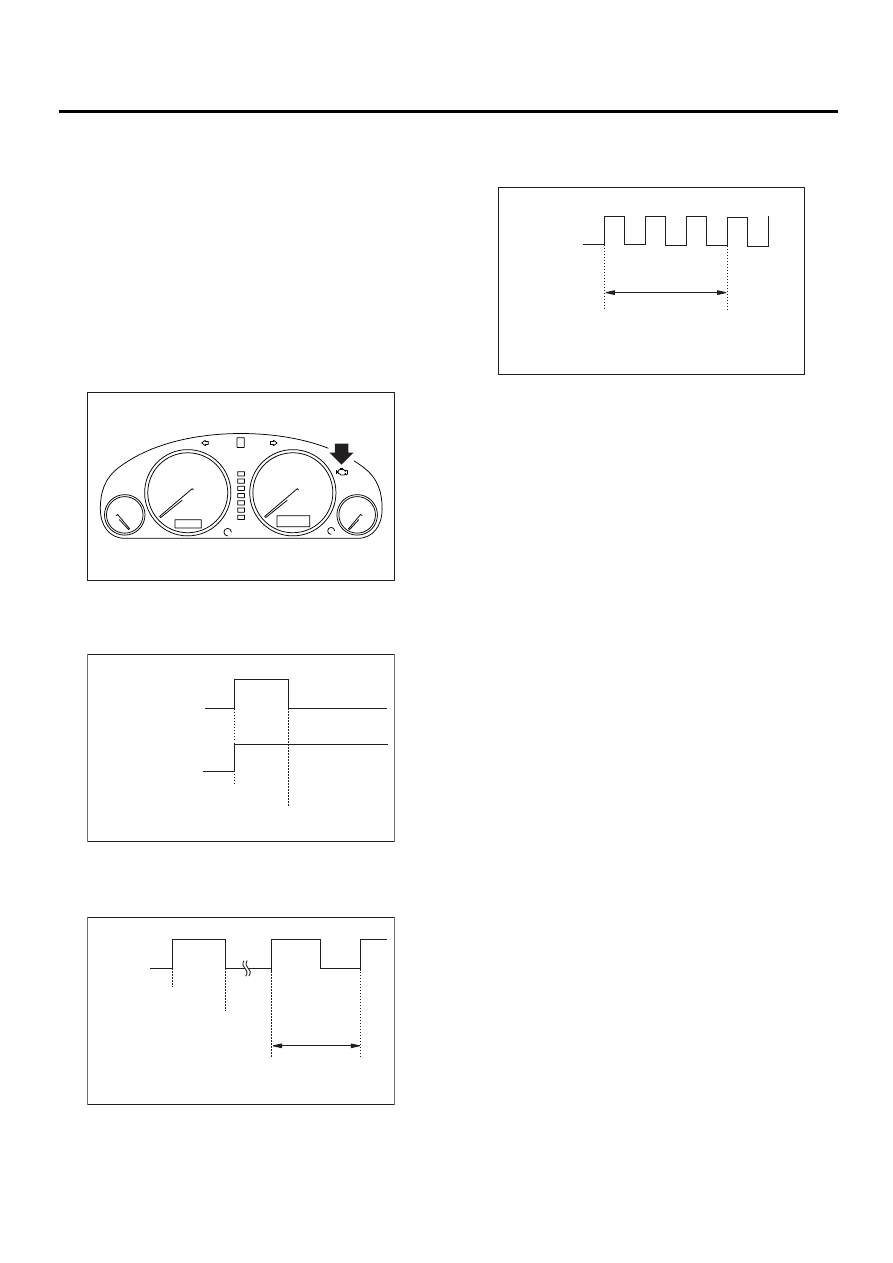
1) When the ignition switch is turned to ON (engine
OFF), the CHECK ENGINE malfunction indicator
lamp (MI) in the combination meter illuminates.
NOTE:
If the MI does not illuminate, perform diagnostics of
the CHECK ENGINE light circuit or the combination
meter circuit. <Ref. to EN(H4DOSTC)-40, CHECK
ENGINE MALFUNCTION INDICATOR LAMP (MI)
DOES NOT COME ON., Engine Malfunction Indi-
cator Lamp (MI).>
2) After starting the engine, the MI goes out. If it
does not, either the engine or emission control sys-
tem is malfunctioning.
3) If the diagnosis system senses a misfire which
could damage the catalyzer, the MI will blink at a
cycle of 1 Hz.
4) When the ignition switch is turned to ON (engine
OFF) or to “START” with the test mode connector
connected, the MI blinks at a cycle of 3 Hz.
EN-01001
EN-00196
a) No trouble
b) Trouble occurs.
ON
MIL
OFF
ON
ON
MIL
OFF
Ignition
switch
Engine
start
EN-00197
ON
MIL
OFF
ON
Ignition
switch
Engine
start
Misfire
start
1 sec.
EN-00198
ON
MIL
OFF
ON
Ignition
switch
1 sec.
EN(H4DOSTC)-40
ENGINE (DIAGNOSTICS)
ENGINE MALFUNCTION INDICATOR LAMP (MI)
C: CHECK ENGINE MALFUNCTION INDICATOR LAMP (MI) DOES NOT COME
ON.
• DIAGNOSIS:
• The CHECK ENGINE malfunction indicator lamp (MI) circuit is open or shorted.
• TROUBLE SYMPTOM:
• When the ignition switch is turned ON (engine OFF), the MI does not come on.
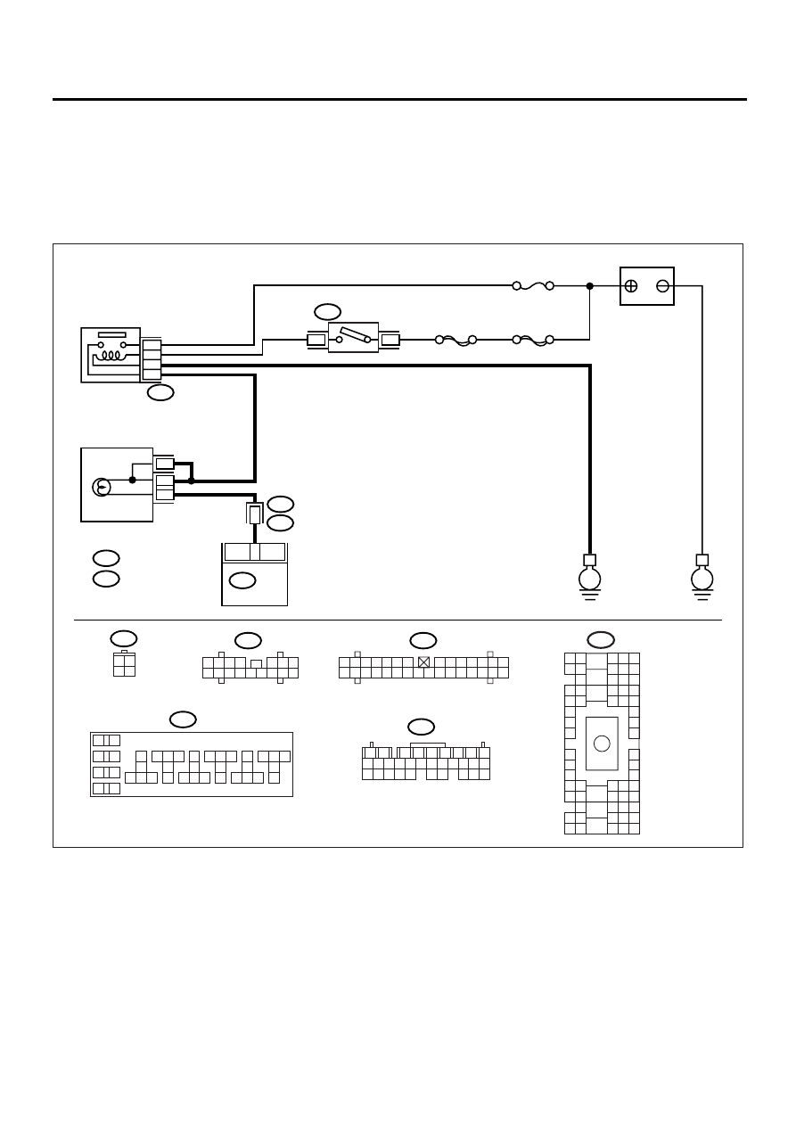
• WIRING DIAGRAM:
EN-00928
BATTERY
IGNITION
SWITCH
IGNITION
RELAY
SBF-4
SBF-1
No.5
B72
B72
B36
B137
B157
ECM
i1
E
E
1
4
37
34
36
38
15
i10
A :
i11
B :
i11
i10
B137
B157
B5
B10
COMBINATION
METER
3 4
1 2
1
2
7
8
9
5
6
3
4
10 11 12
19 20 21
29 30 31
13 14 15 16 17
27 28
18
22 23 24 25 26
10
11 12 13
14 15 16
17
18
19
20
21 22 23
24 25 26
27
28
29
30
31 32 33
34 35 36
37
38
1
2
9
3
4
5
6
7
8
A4
A8
1 2 3
8 9 10
4
11 12 13 14 15 16
5 6 7
1 2 3 4 5 6 7
8 9 10 11 12 13 14
15 16 17 18 19 20 21 22 23 24 25 26 27 28 29 30
B36
B4 B5 B6
A4 A5 A6
C5 C6
F6
D4 D5 D6
F1
H1
C4
G6
G1
C2
K1
M1 M2
K6
L1
D1 D2
A1 A2
B1 B2
I6
J6
L2
I1
J1
H6
M4 M5 M6
L4 L5 L6
N5 N6
O4 O5 O6
N4
P4 P5
N2
O1 O2
P1 P2
N3
O3
P3
P6
A3
B3
C3
E4 E5 E6
E1 E2

EN(H4DOSTC)-41
ENGINE (DIAGNOSTICS)
ENGINE MALFUNCTION INDICATOR LAMP (MI)
Step
Value
Yes
No
1
CHECK OUTPUT SIGNAL FROM ECM.
1) Turn the ignition switch to ON.
2) Measure the voltage between ECM con-
nector and chassis ground.
Connector & terminal
(B137) No. 15 (+) — Chassis ground (
−−−−
):
Is the measured value less than the speci-
fied value?
1 V
2
CHECK POOR CONTACT.
Does the MI come on when shaking or pulling
ECM connector and harness?
MI illuminates.
Repair the poor
contact in ECM
connector.
3
CHECK ECM CONNECTOR.
Is the ECM connector correctly connected?
Connected.
Replace the ECM.
<Ref. to
FU(H4DOSTC)-
40, Engine Con-
trol Module.>
Repair the con-
nection of ECM
connector.
4
CHECK HARNESS BETWEEN COMBINA-
TION METER AND ECM CONNECTOR.
1) Turn the ignition switch to OFF.
2) Remove the combination meter. <Ref. to
IDI-15, Combination Meter Assembly.>
3) Disconnect the connector from ECM and
combination meter.
4) Measure the resistance of harness
between ECM and combination meter con-
nector.
Connector & terminal
(B137) No. 15 — (i11) No. 10:
Is the measured value less than the speci-
fied value?
1
Ω
Repair the har-
ness and connec-
tor.
NOTE:
In this case, repair
the following:
• Open circuit in
harness between
ECM and combi-
nation meter con-
nector
• Poor contact in
coupling connector
5
CHECK POOR CONTACT.
Check poor contact in combination meter con-
nector.
Is there poor contact in combination meter
connector?
There is poor contact.
Repair the poor
contact in combi-
nation meter con-
nector.
Нет комментариевНе стесняйтесь поделиться с нами вашим ценным мнением.
Текст