Subaru Legacy III (2000-2003 year). Service manual — part 469
EN(H4DOSTC)-46
ENGINE (DIAGNOSTICS)
ENGINE MALFUNCTION INDICATOR LAMP (MI)
E: CHECK ENGINE MALFUNCTION INDICATOR LAMP (MI) DOES NOT BLINK
AT A CYCLE OF 3 HZ.
• DIAGNOSIS:
• The CHECK ENGINE malfunction indicator lamp (MI) circuit is open or shorted.
• Test mode connector circuit is in open.
• TROUBLE SYMPTOM:
• When in inspection mode, the MI does not blink at a cycle of 3 Hz.
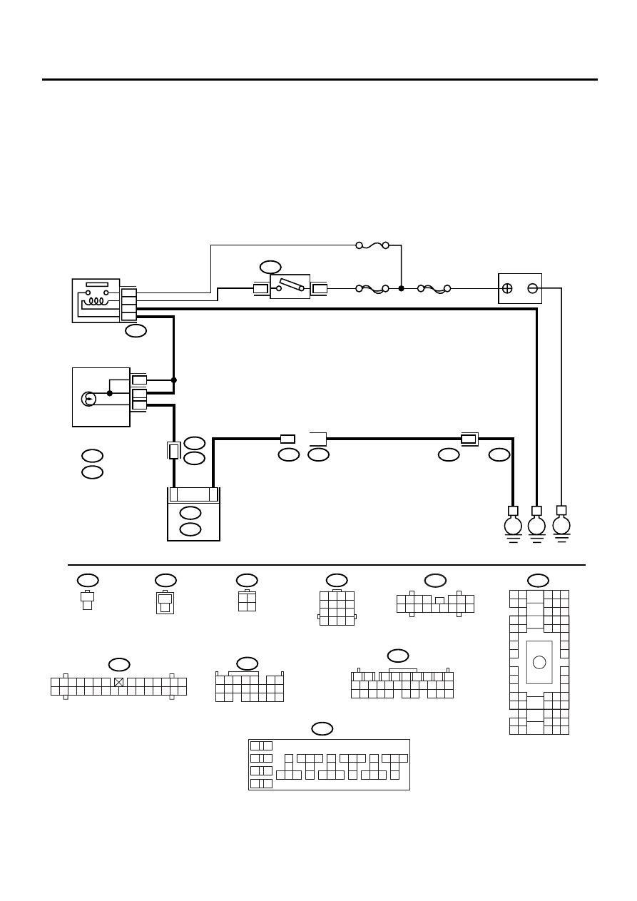
• WIRING DIAGRAM:
EN-00929
BATTERY
IGNITION
SWITCH
IGNITION
RELAY
SBF-4
SBF-1
No.5
B72
B36
B75
B76
E3
B22
B134
B137
B157
ECM
i1
E
E
E
1
4
16
1
1
37
34
36
38
B15
A5
i10
A :
i11
B :
A :
B :
B5
B10
COMBINATION
METER
B72
B22
B75
B134
B76
i10
B137
B157
B36
3 4
1 2
1
2
7
8
9
5
6
3
4
10 11 12
19 20 21
29 30 31
13 14 15 16 17
27 28
18
22 23 24 25 26
10
11 12 13
14 15 16
17
18
19
20
21 22 23
24 25 26
27
28
29
30
31 32 33
34 35 36
37
38
1
2
9
3
4
5
6
7
8
1 2 3 4
10 11 12
19 20 21
13
5
6
14 15
7
8 9
16 17
18
22
1 2 3 4
5 6 7 8
9 10 11 12
13 14 15 16
1
2
1
2
1
2
1
2
A8
A4
1 2 3
8 9 10
4
11 12 13 14 15 16
5 6 7
i11
B4 B5 B6
A4 A5 A6
C5 C6
F6
D4 D5 D6
F1
H1
C4
G6
G1
C2
K1
M1 M2
K6
L1
D1 D2
A1 A2
B1 B2
I6
J6
L2
I1
J1
H6
M4 M5 M6
L4 L5 L6
N5 N6
O4 O5 O6
N4
P4 P5
N2
O1 O2
P1 P2
N3
O3
P3
P6
A3
B3
C3
E4 E5 E6
E1 E2
1 2 3 4 5 6 7
8 9 10 11 12 13 14
15 16 17 18 19 20 21 22 23 24 25 26 27 28 29 30

EN(H4DOSTC)-47
ENGINE (DIAGNOSTICS)
ENGINE MALFUNCTION INDICATOR LAMP (MI)
Step
Value
Yes
No
1
CHECK STATUS OF CHECK ENGINE MAL-
FUNCTION INDICATOR LAMP (MI).
1) Turn the ignition switch to OFF.
2) Disconnect the test mode connector.
3) Turn the ignition switch to ON. (engine
OFF)
Does the MI come on?
MI illuminates.
Repair the MI cir-
cuit. <Ref. to
EN(H4DOSTC)-
40, CHECK
ENGINE MAL-
FUNCTION INDI-
CATOR LAMP
(MI) DOES NOT
COME ON.,
Engine Malfunc-
tion Indicator
Lamp (MI).>
2
CHECK HARNESS BETWEEN COMBINA-
TION METER AND ECM CONNECTOR.
1) Turn the ignition switch to OFF.
2) Disconnect the connector from ECM.
3) Turn the ignition switch to ON.
Does the MI come on?
MI illuminates.
Repair the ground
short circuit in har-
ness between
combination meter
and ECM connec-
tor.
3
CHECK HARNESS BETWEEN TEST MODE
CONNECTOR AND CHASSIS GROUND.
1) Turn the ignition switch to OFF.
2) Disconnect the connector from ECM.
3) Measure the resistance of harness
between test mode connector and chassis
ground.
Connector & terminal
(B76) No. 1 — Chassis ground:
Is the measured value less than the speci-
fied value?
1
Ω
Repair the har-
ness and connec-
tor.
NOTE:
In this case, repair
the following:
• Open circuit in
harness between
test mode connec-
tor and chassis
ground
4
CHECK POOR CONTACT.
Check poor contact in ECM connector.
Is there poor contact in ECM connector?
There is poor contact.
Repair the poor
contact in ECM
connector.
5
CHECK HARNESS BETWEEN ECM AND
TEST MODE CONNECTOR.
1) Connect the test mode connector.
2) Measure the resistance of harness
between ECM and chassis ground.
Connector & terminal
(B134) No. 5 — Chassis ground:
Is the measured value less than the speci-
fied value?
1
Ω
Repair the open
circuit in harness
between ECM and
test mode connec-
tor.
6
CHECK POOR CONTACT.
Check poor contact in ECM connector.
Is there poor contact in ECM connector?
There is poor contact.
Repair the poor
contact in ECM
connector.
Replace the ECM.
<Ref. to
FU(H4DOSTC)-
40, Engine Con-
trol Module.>
EN(H4DOSTC)-48
ENGINE (DIAGNOSTICS)
ENGINE MALFUNCTION INDICATOR LAMP (MI)
F: CHECK ENGINE MALFUNCTION INDICATOR LAMP (MI) REMAINS BLINK-
ING AT A CYCLE OF 3 HZ.
• DIAGNOSIS:
• Test mode connector circuit is shorted.
• TROUBLE SYMPTOM:
• MI blinks at a cycle of 3 Hz when the ignition switch is turned to ON.
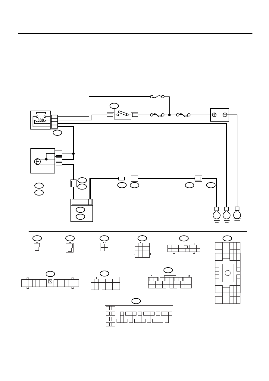
• WIRING DIAGRAM:
EN-00929
BATTERY
IGNITION
SWITCH
IGNITION
RELAY
SBF-4
SBF-1
No.5
B72
B36
B75
B76
E3
B22
B134
B137
B157
ECM
i1
E
E
E
1
4
16
1
1
37
34
36
38
B15
A5
i10
A :
i11
B :
A :
B :
B5
B10
COMBINATION
METER
B72
B22
B75
B134
B76
i10
B137
B157
B36
3 4
1 2
1
2
7
8
9
5
6
3
4
10 11 12
19 20 21
29 30 31
13 14 15 16 17
27 28
18
22 23 24 25 26
10
11 12 13
14 15 16
17
18
19
20
21 22 23
24 25 26
27
28
29
30
31 32 33
34 35 36
37
38
1
2
9
3
4
5
6
7
8
1 2 3 4
10 11 12
19 20 21
13
5
6
14 15
7
8 9
16 17
18
22
1 2 3 4
5 6 7 8
9 10 11 12
13 14 15 16
1
2
1
2
1
2
1
2
A8
A4
1 2 3
8 9 10
4
11 12 13 14 15 16
5 6 7
i11
B4 B5 B6
A4 A5 A6
C5 C6
F6
D4 D5 D6
F1
H1
C4
G6
G1
C2
K1
M1 M2
K6
L1
D1 D2
A1 A2
B1 B2
I6
J6
L2
I1
J1
H6
M4 M5 M6
L4 L5 L6
N5 N6
O4 O5 O6
N4
P4 P5
N2
O1 O2
P1 P2
N3
O3
P3
P6
A3
B3
C3
E4 E5 E6
E1 E2
1 2 3 4 5 6 7
8 9 10 11 12 13 14
15 16 17 18 19 20 21 22 23 24 25 26 27 28 29 30
EN(H4DOSTC)-49
ENGINE (DIAGNOSTICS)
ENGINE MALFUNCTION INDICATOR LAMP (MI)
Step
Value
Yes
No
1
CHECK TEST MODE CONNECTOR.
1) Disconnect the test mode connector.
2) Turn the ignition switch to ON.
Does the MI flash on and off?
MI flashes.
System is in good
order.
NOTE:
MI blinks at a cycle
of 3 Hz when test
mode connector is
connected.
2
CHECK HARNESS BETWEEN ECM CON-
NECTOR AND ENGINE GROUNDING TER-
MINAL.
1) Turn the ignition switch to OFF.
2) Disconnect the connector from ECM.
3) Measure the resistance of harness
between ECM connector and chassis
ground.
Connector & terminal
(B134) No. 5 — Chassis ground:
Does the measured value exceed the spec-
ified value?
1 M
Ω
Replace the ECM.
<Ref. to
FU(H4DOSTC)-
40, Engine Con-
trol Module.>
Repair the short
circuit in harness
between ECM and
test mode connec-
tor.
Нет комментариевНе стесняйтесь поделиться с нами вашим ценным мнением.
Текст