Subaru Legacy III (2000-2003 year). Service manual — part 965

SL-16
SECURITY AND LOCKS
KEYLESS ENTRY SYSTEM
7. CHECK KEY WARNING SWITCH
Step
Value
Yes
No
1
CHECK FUSE.
Remove and visually check fuse No. 6 (in the
main fuse box).
Is the fuse blown?
The fuse is not blown.
Replace the fuse
with a new one.
2
CHECK KEY WARNING SWITCH CIRCUIT.
1) Disconnect the keyless entry control mod-
ule harness connector.
2) Insert the key into the ignition switch.
(LOCK position)
3) Measure the voltage between the harness
connector terminal and chassis ground.
Connector & terminal
(B176) No. 1 (+) — chassis ground (–):
Does the measured value exceed the spec-
ified value?
10 V
3
CHECK KEY WARNING SWITCH CIRCUIT.
1) Remove the key from the ignition switch.
2) Measure the voltage between the harness
connector terminal and chassis ground.
Connector & terminal
(B176) No. 1 (+) — chassis ground (–):
Is the measured value same as the speci-
fied value?
0 V
The key warning
switch is OK.
4
CHECK KEY WARNING SWITCH.
1) Disconnect the key warning switch harness
connector.
2) Insert the key into the ignition switch.
(LOCK position)
3) Measure the resistance between the key
warning switch terminals.
Terminal
No. 1 — No. 2:
Is the measured value less than the speci-
fied value?
1
Ω
Replace key warn-
ing switch.
5
CHECK KEY WARNING SWITCH.
1) Remove the key from the ignition switch.
2) Measure the resistance between the key
warning switch terminals.
Terminal
No. 1 — No. 2:
Does the measured value exceed the spec-
ified value?
1 M
Ω
Check the follow-
ing:
•
Harness for
open circuits or
shorts between
the key warning
switch and fuse
•
Harness for
open circuits or
shorts between
the keyless entry
control module
and key warning
switch
Replace key warn-
ing switch.

SL-17
SECURITY AND LOCKS
KEYLESS ENTRY SYSTEM
8. CHECK HAZARD LIGHT OPERATION
9. CHECK ROOM LIGHT OPERATION
Step
Value
Yes
No
1
CHECK HAZARD LIGHT OPERATION.
Make sure the hazard light blinks when hazard
switch is turned ON.
Does hazard light brink?
Hazard light blinks.
Check hazard light
circuit.
2
CHECK OUTPUT SIGNAL.
1) Remove the key from ignition switch.
2) Close all doors and rear gate.
3) Measure voltage between keyless entry
control module harness connector terminal
and chassis ground when LOCK or OPEN
button of transmitter is pressed.
Connector & terminal
(B176) No. 12, No. 13 (+) — Chassis
ground (
−
):
Does the measured value exceed the spec-
ified value?
10 V
Check harness for
open or short
between keyless
entry control mod-
ule and turn signal
lights.
Replace the key-
less entry control
module.
Step
Value
Yes
No
1
CHECK ROOM LIGHT OPERATION.
Make sure the room light illuminates when the
room light switch is turned ON.
Does the room light illuminate?
Room light illuminates.
Check the room
light circuit.
2
CHECK HARNESS BETWEEN ROOM LIGHT
AND KEYLESS ENTRY CONTROL MODULE.
1) Disconnect the keyless entry control mod-
ule harness connector and room light har-
ness connector.
2) Measure the resistance between the key-
less entry control module harness connec-
tor terminal and the room light harness
connector terminal.
Connector & terminal
(B176) No. 11 — (R52) No. 2:
Is the measured value less than the speci-
fied value?
10
Ω
The room light
operation circuit is
OK.
Check the harness
for open circuits or
shorts between
the keyless entry
control module
and room light.

SL-18
SECURITY AND LOCKS
KEYLESS ENTRY SYSTEM
10.CHECK IGNITION SWITCH ILLUMINATION CIRCUIT
Step
Value
Yes
No
1
CHECK IGNITION SWITCH ILLUMINATION
POWER SUPPLY.
1) Disconnect the ignition switch illumination
harness connector.
2) Measure voltage between the ignition
switch illumination harness connector ter-
minal and chassis ground.
Connector & terminal
(B224) No. 2 (+) — Chassis ground (
−
):
Does the measured value exceed the spec-
ified value?
10 V
Check harness for
open circuit or
shorts between
the ignition switch
illumination and
fuse.
2
CHECK HARNESS BETWEEN IGNITION
SWITCH ILLUMINATION AND KEYLESS EN-
TRY CONTROL MODULE.
1) Disconnect the keyless entry control mod-
ule harness connector.
2) Measure the resistance between the key-
less entry harness connector terminal and
the ignition switch illumination harness con-
nector.
Connector & terminal
(B176) No. 11 — (B224) No. 1:
Is the measured value less than the speci-
fied value?
10
Ω
Check the ignition
switch illumina-
tion. If NG, replace
the ignition switch
illumination.
Repair the har-
ness.
SL-19
SECURITY AND LOCKS
FRONT INNER REMOTE
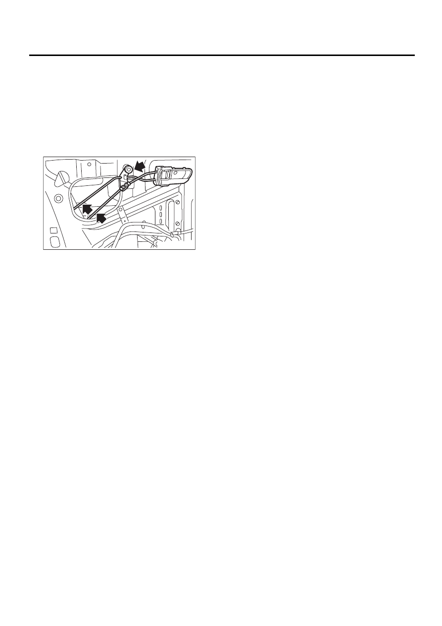
4. Front Inner Remote
A: REMOVAL
1) Remove the door trim. <Ref. to EI-30, REMOV-
AL, Front Door Trim.>
2) Remove the sealing cover. <Ref. to EB-13, RE-
MOVAL, Front Sealing Cover.>
3) Remove the two rod joints.
4) Remove the screw, and detach the front inner
remote.
B: INSTALLATION
Install in the reverse order of removal.
NOTE:
Make sure the inner remote works properly after in-
stallation.
C: INSPECTION
1) Make sure the rod is not deformed.
2) Make sure the lever and rod work smoothly.
SL-00072
Нет комментариевНе стесняйтесь поделиться с нами вашим ценным мнением.
Текст