Subaru Legacy III (2000-2003 year). Service manual — part 227
EN(H4SOw/oOBD)-98
ENGINE (DIAGNOSTICS)
DIAGNOSTIC PROCEDURE WITH DIAGNOSTIC TROUBLE CODE (DTC)
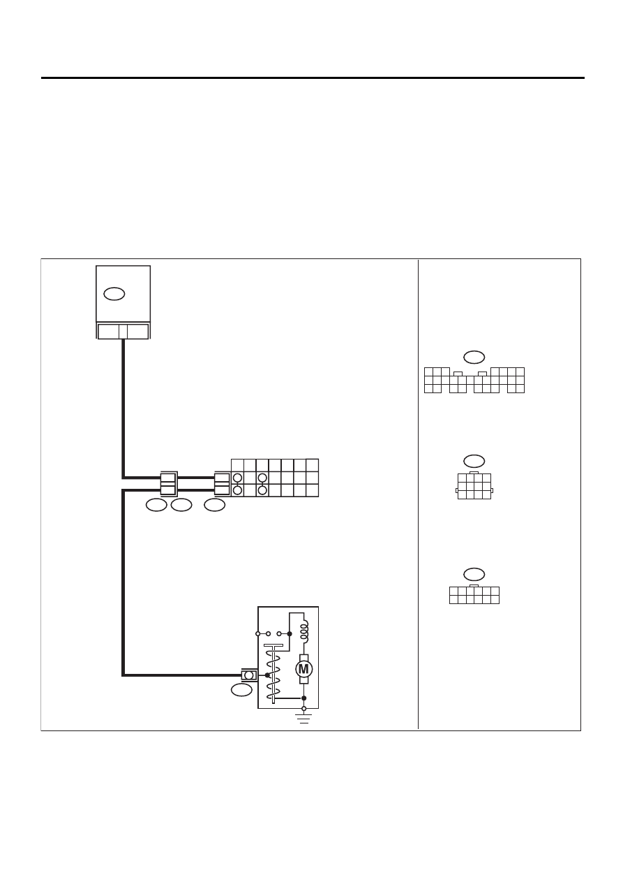
P: DTC 51 PARK/NEUTRAL POSITION SWITCH (AT VEHICLE)
• DIAGNOSIS:
• The park/neutral position switch signal is abnormal.
• The shift cable is connected abnormally.
• The harness connector between ECM and inhibitor switch is in short or open.
• TROUBLE SYMPTOM:
• Erroneous idling
CAUTION:
After repair or replacement of faulty parts, conduct CLEAR MEMORY and INSPECTION MODES. <Ref.
to EN(H4SOw/oOBD)-28, OPERATION, Clear Memory Mode.> and <Ref. to EN(H4SOw/oOBD)-26, OP-
ERATION, Inspection Mode.>
• WIRING DIAGRAM:
EN-01063
12
INHIBITOR SWITCH
7
P
R
N
D
3
2
1
12
11
T7
T3
B12
B14
5 6 7
8
2
1
9
4
3
10
24
22 23
25
11 12 13 14 15
26
27 28
16 17 18 19
20 21
B135
T7
1 2 3 4 5 6
7 8 9 10 11 12
26
B135
ECM
STARTER MOTOR
B12
1 2 3 4
5 6 7 8
9 10 11 12

EN(H4SOw/oOBD)-99
ENGINE (DIAGNOSTICS)
DIAGNOSTIC PROCEDURE WITH DIAGNOSTIC TROUBLE CODE (DTC)
Step
Value
Yes
No
1
CHECK INPUT SIGNAL FOR ECM.
1) Turn ignition switch to ON.
2) Measure voltage between ECM and chas-
sis ground in selector lever “N” and “P”
positions.
Connector & terminal
(B135) No. 26 (+) — Chassis ground (
−−−−
):
Is the measured value less than the speci-
fied value?
1 V
2
CHECK POOR CONTACT.
Check poor contact in ECM connector.
Is there poor contact in ECM connector?
There is poor contact.
Repair poor con-
tact in ECM con-
nector.
3
CHECK HARNESS BETWEEN ECM AND IN-
HIBITOR SWITCH CONNECTOR.
1) Turn ignition switch to OFF.
2) Disconnect connectors from ECM and
inhibitor switch.
3) Measure resistance of harness between
ECM and inhibitor switch connector.
Connector & terminal
(B135) No. 26 — (T7) No. 12:
Is the measured value less than the speci-
fied value?
1
Ω
Repair harness
and connector.
NOTE:
In this case, repair
the following:
• Open circuit in
harness between
ECM and inhibitor
switch connector
• Poor contact in
coupling connector
(B12)
• Poor contact in
inhibitor switch
connector
• Poor contact in
ECM connector
4
CHECK HARNESS BETWEEN ECM AND
TRANSMISSION HARNESS CONNECTOR.
Measure resistance of harness between ECM
connector and chassis ground.
Connector & terminal
(B135) No. 26 — Chassis ground:
Is the measured value less than the specified
value?
10
Ω
Repair ground
short circuit in har-
ness between
ECM and trans-
mission harness
connector.
5
CHECK INHIBITOR SWITCH GROUND LINE.
Remove re-starter motor connector.
Measure resistance of harness between inhibi-
tor switch connector and engine ground.
Connector & terminal
(T7) No. 12 — (B14) No. 1:
Is the measured value less than the specified
value?
5
Ω
Repair open circuit
in inhibitor switch
ground line.
6
CHECK STARTER MOTOR.
Check starter motor. <Ref. to SC(H4SO)-10,
INSPECTION, Starter.>
Starter motor is normal.
Repair or replace
starter motor.
7
CHECK POOR CONTACT.
Check poor contact in ECM connector.
Is there poor contact in ECM connector?
There is poor contact.
Repair poor con-
tact in ECM con-
nector.
Replace ECM.
<Ref. to
FU(H4SOw/
oOBD)-42, Engine
Control Module.>
EN(H4SOw/oOBD)-100
ENGINE (DIAGNOSTICS)
DIAGNOSTIC PROCEDURE WITH DIAGNOSTIC TROUBLE CODE (DTC)
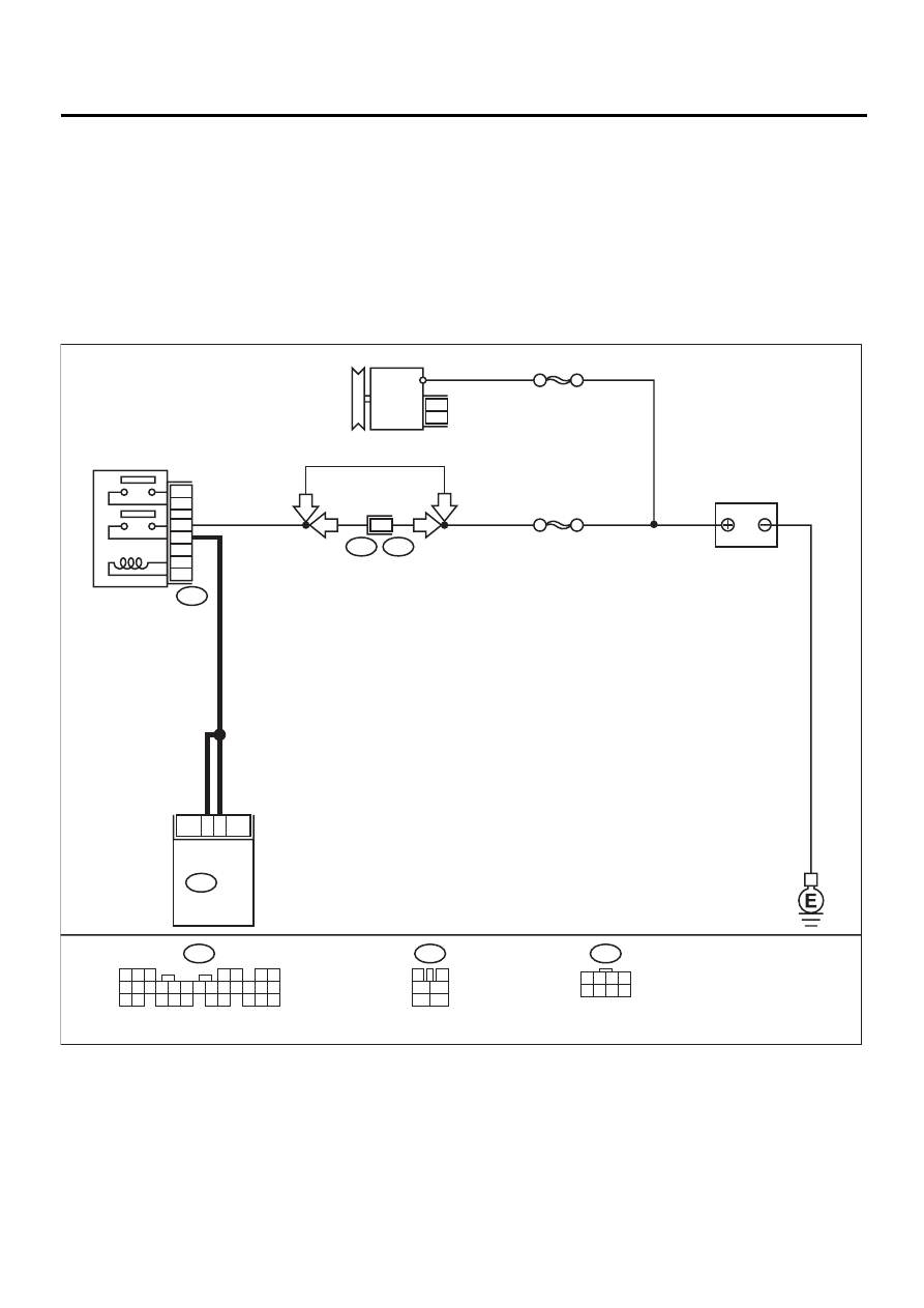
Q: DTC 85 CHARGE SYSTEM
• DIAGNOSIS:
• Power source voltage of the ECM is low or high.
• TROUBLE SYMPTOM:
• Charge warning light comes on.
CAUTION:
After repair or replacement of faulty parts, conduct CLEAR MEMORY and INSPECTION MODES. <Ref.
to EN(H4SOw/oOBD)-28, OPERATION, Clear Memory Mode.> and <Ref. to EN(H4SOw/oOBD)-26, OP-
ERATION, Inspection Mode.>
• WIRING DIAGRAM:
EN-01064
2
1
F44
B61
ECM
B47
B136
3
4
1
2
5
6
B136
F44
B47
SBF-5
SBF-1
BATTERY
MAIN RELAY
1
2
3
5
4
6
6
LHD
LHD
RHD
RHD
GENERATOR
1 2 3 4
5 6 7 8
5
4
6 7
8
2
1
9
3
10
22
23
11 12 13 14 15
24 25
26 27
16 17 18
28 29
19 20
21
30

EN(H4SOw/oOBD)-101
ENGINE (DIAGNOSTICS)
DIAGNOSTIC PROCEDURE WITH DIAGNOSTIC TROUBLE CODE (DTC)
Step
Value
Yes
No
1
CHECK GENERATOR.
1) Start engine.
2) Idling after warm-up.
3) Measure voltage between generator B ter-
minal and chassis ground.
Terminal
Generator B terminal (+) — Chassis
ground (–):
Is the measured value within the specified
value?
10.8 V — 16.2 V
Repair generator.
<Ref. to
SC(H4SO)-14,
Generator.>
2
CHECK GENERATOR.
1) Run engine at 5,000 rpm.
2) Measure voltage between generator B ter-
minal and chassis ground.
Terminal
Generator B terminal (+) — Chassis
ground (
−−−−
):
Is the measured value within the specified
value?
10.8 V — 16.2 V
Repair generator.
<Ref. to
SC(H4SO)-14,
Generator.>
3
CHECK BATTERY TERMINAL.
Turn ignition switch to OFF.
Are the positive and negative battery terminals
tightly clamped?
Battery terminal is tightly
clamped.
Tighten the clamp
of terminal.
4
CHECK INPUT VOLTAGE OF ECM.
1) Run the engine at idle.
2) Measure voltage between ECM connector
and chassis ground.
Connector & terminal
(B136) No. 1 (+) — Chassis ground (
−−−−
):
(B136) No. 2 (+) — Chassis ground (
−−−−
):
Is the measured value within the specified
value?
10.8 V — 16.2 V
Repair harness
connector
between battery,
main relay and
ECM.
5
CHECK POOR CONTACT IN CONNECTORS.
Is there poor contact in connectors between
generator, battery and ECM?
There is poor contact.
Repair connector.
6
CHECK ECM.
1) Connect all connectors.
2) Erase the memory. <Ref. to EN(H4SOw/
oOBD)-28, OPERATION, Clear Memory
Mode.>
3) Perform inspection mode. <Ref. to
EN(H4SOw/oOBD)-26, OPERATION,
Inspection Mode.>
4) Read out the trouble code. <Ref. to
EN(H4SOw/oOBD)-24, OPERATION,
Read Diagnostic Trouble Code (DTC).>
Is the same trouble code (DTC) as in the
current diagnosis still being output?
DTC 85 is displayed.
Replace genera-
tor.
7
CHECK ANY OTHER TROUBLE CODES AP-
PEARANCE.
Are other trouble codes (DTC) being output?
DTC is displayed.
Proceed with the
diagnosis corre-
sponding to the
trouble code.
A temporary poor
contact.
Нет комментариевНе стесняйтесь поделиться с нами вашим ценным мнением.
Текст