Subaru Legacy III (2000-2003 year). Service manual — part 1004

CC-36
CRUISE CONTROL SYSTEM (DIAGNOSTICS)
DIAGNOSTICS CHART WITH TROUBLE CODE
F: DTC 38 MOTOR DRIVE SHAFT DOES NOT ENGAGE PROPERLY.
G: DTC 39 MOTOR IS OVERLOADED.
Step
Value
Yes
No
1
CHECK ACTUATOR MOTOR.
1) Turn ignition switch to OFF.
2) Disconnect harness connector from cruise
control actuator.
3) Remove cruise control actuator from
mounting bracket.
4) Pull cable by hand to check for looseness
or status of inner gear engagement.
Are foreign particles caught in inner gear or
does inner gear engage and disengage
improperly?
Cable and inner gear are OK.
Replace cruise
control actuator.
<Ref. to CC-4,
Actuator.>
Check the cruise
control cable
adjustment.<Ref.
to CC-6, CABLE
FREE PLAY,
INSPECTION,
General Descrip-
tion.>
Step
Value
Yes
No
1
CHECK THE OPERATING CURRENT TO AC-
TUATOR MOTOR.
1) Connect Subaru Select Monitor to data link
connector.
2) Try to drive the vehicle while operating the
cruise control system.
3) Measure the operation current to the cruise
control actuator motor.
Is the measured value less than the speci-
fied value?
10 A
Replace cruise
control module.
<Ref. to CC-6,
Cruise Control
Module.>
Check the power
supply circuit.
<Ref. to CC-14,
CHECK POWER
SUPPLY, Diag-
nostics Chart with
Symptom.>

IMMOBILIZER (DIAGNOSTICS)
IM
Page
Basic Diagnostic Procedure . . . . . . . . . . . . . . . . . . 2
General Description . . . . . . . . . . . . . . . . . . . . . 3
Electrical Components Location. . . . . . . . . . . . . . . . ..5
Immobilizer Control Module I/O Signal. . . . . . . . . . . . . . 6
Subaru Select Monitor. . . . . . . . . . . . . . . . . . . . .7
Read Diagnostic Trouble Code (DTC) . . . . . . . . . . . . . . 8
Clear Memory Mode. . . . . . . . . . . . . . . . . . . . . 9
Diagnostic Procedure for Immobilizer Indicator Light. . . . . . . . 10
List of Diagnostic Trouble Code (DTC) . . . . . . . . . . . . . .16
Diagnostic Procedure with Trouble Code (DTC) . . . . . . . . . ...17

IM-2
IMMOBILIZER (DIAGNOSTICS)
BASIC DIAGNOSTIC PROCEDURE
1. Basic Diagnostic Procedure
A: PROCEDURE
Step
Value
Yes
No
1
CHECK ILLUMINATION OF IMMOBILIZER
INDICATOR LIGHT.
1) Turn ignition switch to OFF or ACC posi-
tion.
2) Wait at least 60 seconds.
Does immobilizer indicator light blink?
Immobilizer indicator light
blinks.
Check immobi-
lizer indicator light
circuit.<Ref. to IM-
10, CHECK
IMMOBILIZER
INDICATOR CIR-
CUIT, INSPEC-
TION, Diagnostic
Procedure for
Immobilizer Indica-
tor Light.>
2
CHECK ILLUMINATION OF IMMOBILIZER
INDICATOR LIGHT.
Remove key from ignition switch.
Does immobilizer indicator light begin to blink 1
second after the key is removed?
Immobilizer indicator light
begins to blink.
Check key switch
circuit. <Ref. to IM-
14, CHECK KEY
SWITCH CIR-
CUIT, INSPEC-
TION, Diagnostic
Procedure for
Immobilizer Indica-
tor Light.>
3
CHECK ENGINE START.
Turn ignition switch to START position.
Is the engine hard to start?
The engine starts.
4
CHECK ILLUMINATION OF IMMOBILIZER
INDICATOR LIGHT.
Turn ignition switch ON.
Does immobilizer indicator light illuminate?
Immobilizer indicator light illu-
minates.
Check immobi-
lizer indicator light
circuit.<Ref. to IM-
10, CHECK
IMMOBILIZER
INDICATOR CIR-
CUIT, INSPEC-
TION, Diagnostic
Procedure for
Immobilizer Indica-
tor Light.>
Immobilizer sys-
tem is normal.
5
CHECK INDICATION OF DTC ON DISPLAY.
1) Turn ignition switch OFF.
2) Connect the Subaru Select Monitor to data
link connector. <Ref. to IM-7, HOW TO
USE SUBARU SELECT MONITOR,
OPERATION, Subaru Select Monitor.>
3) Turn ignition switch and Subaru Select
Monitor switch ON.
4) Read DTC on the display.
Is DTC indicated on display?
DTC is indicated on display.
Check DTC. <Ref.
to IM-16, List of
Diagnostic Trou-
ble Code (DTC).>
Go to step 6.
Check engine
starting failure.
6
PERFORM THE DIAGNOSIS.
1) Inspect using “Diagnostic Procedure with
Trouble Code (DTC)”.<Ref. to IM-17, Diag-
nostic Procedure with Trouble Code
(DTC).>
2) Repair the trouble cause.
3) Perform clear memory mode.
4) Read DTC again.
Is DTC indicated on display?
DTC is indicated on display.
Inspect using
“Diagnostic Proce-
dure with Trouble
Code”. <Ref. to
IM-17, Diagnostic
Procedure with
Trouble Code
(DTC).>
Finish the diag-
nostics.
IM-3
IMMOBILIZER (DIAGNOSTICS)
GENERAL DESCRIPTION
2. General Description
A: CAUTION
CAUTION:
• Airbag system wiring harness is routed near
the immobilizer control module. All airbag sys-
tem wiring harness and connectors are colored
yellow. Do not use electrical test equipment on
these circuits.
• Be careful not to damage airbag system wir-
ing harness when servicing the immobilizer
control module.
• While diagnostic items are being checked, do
not operate radios, portable telephones, etc.
which emit electromagnetic waves near or
inside the vehicle.
• When ignition switch is being turned ON or
OFF while diagnostic items are being checked,
do not allow keys with different ID codes close
to the ignition switch. If ignition key is in a key
holder, remove it from holder before carrying
out diagnoses.
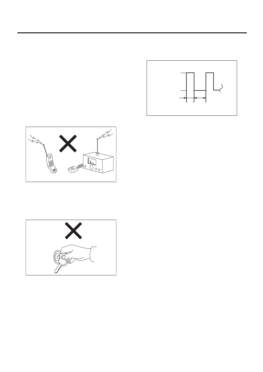
• When repeatedly turning ignition ON or OFF
while diagnostic items are being checked, it
should be switched in cycles of “ON” for at
least 5 seconds
→
→
→
→
“OFF” for at least 8 seconds.
• If engine fails to start with a registered
ignition key, detach ignition key from ignition
switch and wait for approximately 1 second
until immobilizer indicator light begins to flash.
Start engine again.
• Before checking diagnostic items, obtain all
keys for vehicle to be checked possessed by
owner.
IM-00037
IM-00038
(1) Ignition switch position
(2) SEC.
IM-00039
ON
OFF
5
8
( 1 )
( 2 )
Нет комментариевНе стесняйтесь поделиться с нами вашим ценным мнением.
Текст