Subaru Legacy III (2000-2003 year). Service manual — part 907

AB-54
AIRBAG SYSTEM (DIAGNOSTICS)
DIAGNOSTIC CHART WITH DIAGNOSTIC TROUBLE CODE (DTC)
5
CHECK AIRBAG MAIN HARNESS.
1) Remove the instrument panel. <Ref. to EI-
35, Instrument Panel Assembly.>
2) Disconnect connector (AB11) from (AB12),
and connect connector (2F) in test harness
F to (AB11).
3) Measure the resistance between connector
(3I) in test harness I2 and connector (3F) in
test harness F.
Connector & terminal
(3I) No. 3 — (3F) No. 6:
(3I) No. 1 — (3F) No. 5:
Is the measured value less than the speci-
fied value?
10
Ω
Replace the airbag
main harness.
<Ref. to AB-15,
Main Harness.>
6
CHECK AIRBAG MAIN HARNESS.
Measure the resistance between connector
(3I) in the test harness I2 and the chassis
ground.
Connector & terminal
(3I) No. 3 — Chassis ground:
(3I) No. 1 — Chassis ground:
Does the measured value exceed the specified
value?
1 M
Ω
Replace the airbag
main harness.
<Ref. to AB-15,
Main Harness.>
7
CHECK FRONT SUB-SENSOR HARNESS
(LH).
1) Connect connector (1F) in test harness F to
connector (AB12).
2) Measure the resistance between connector
(3H) in test harness H and connector (3F)
in test harness F.
Connector & terminal
(3F) No. 3 — (3H) No. 5:
(3F) No. 4 — (3H) No. 6:
Is the measured value less than the speci-
fied value?
10
Ω
Replace the front
sub-sensor har-
ness (LH). <Ref. to
AB-15, Main Har-
ness.>
8
CHECK FRONT SUB-SENSOR HARNESS
(LH).
Measure the resistance between connector
(3F) in test harness F and the chassis ground.
Connector & terminal
(3F) No. 3 — Chassis ground:
(3F) No. 4 — Chassis ground:
Does the measured value exceed the specified
value?
1 M
Ω
Replace the front
sub-sensor har-
ness (LH). <Ref. to
AB-15, Main Har-
ness.>
9
CHECK FRONT SUB-SENSOR (LH).
1) Connect connector (2H) in test harness H
to front sub-sensor (LH).
2) Measure the resistance of the connector
(3H) in test harness H.
Connector & terminal
(3H) No. 3 — No. 4:
Is the measured value within the specified
range?
750
Ω
— 1 K
Ω
Replace the front
sub-sensor (LH).
<Ref. to AB-20,
Front Sub Sen-
sor.>
Step
Value
Yes
No

AB-55
AIRBAG SYSTEM (DIAGNOSTICS)
DIAGNOSTIC CHART WITH DIAGNOSTIC TROUBLE CODE (DTC)
10
CHECK FRONT SUB-SENSOR (LH).
Measure the resistance between connector
(3H) in test harness H and the chassis ground.
Connector & terminal
(3H) No. 3 — Chassis ground:
(3H) No. 4 — Chassis ground:
Does the measured value exceed the specified
value?
1 M
Ω
Finish the diagno-
sis.
Replace the front
sub-sensor (LH).
<Ref. to AB-20,
Front Sub Sen-
sor.>
Step
Value
Yes
No
AB-56
AIRBAG SYSTEM (DIAGNOSTICS)
DIAGNOSTIC CHART WITH DIAGNOSTIC TROUBLE CODE (DTC)
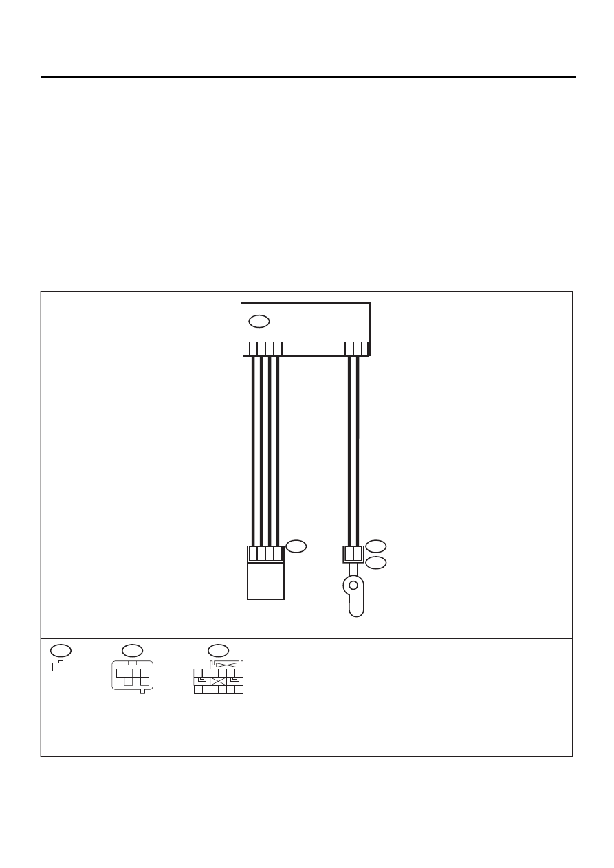
L: DTC 41
DIAGNOSIS:
• Side airbag harness (RH) is faulty.
• Side airbag module (RH) is faulty.
• Airbag control module is faulty.
CAUTION:
• Before diagnosing the airbag system, be sure to turn the ignition switch OFF, disconnect the
ground cable from the battery, and wait more than 20 seconds before starting to work.
• Before replacing the airbag module, roll connector, control module, and sensor, reconnect each
part and confirm that the warning light operates properly.
• When inspecting the airbag main harness, disconnect the driver's airbag module and passenger's
airbag module connectors for safety reasons.
• When inspecting the side airbag harness, disconnect the side airbag module connector and seat
belt pretensioner connector for the safety reasons.
WIRING DIAGRAM:
10
9
7
12
2
1
1
2
AIRBAG CONTROL MODULE
AB18
AB24
AB28
AB25
AB24
AB28
AB18
1 2
1
4
2
3
SIDE AIRBAG
SENSOR RH
INFLATOR
(SIDE RH)
3
4
1
2
1 2 3 4 5 6
7 8 9 10 11 12
AB-00299

AB-57
AIRBAG SYSTEM (DIAGNOSTICS)
DIAGNOSTIC CHART WITH DIAGNOSTIC TROUBLE CODE (DTC)
Step
Value
Yes
No
1
CHECK SIDE AIRBAG MODULE.
1) Turn the ignition switch OFF, disconnect
the battery ground cable, and wait more
than 20 seconds.
2) Disconnect the connector (AB26) from the
seat belt pretensioner (RH). <Ref. to AB-
17, REMOVAL, Airbag Control Module.>
3) Disconnect connector (AB25) from (AB24),
and connect connector (1F) in test harness
F to (AB24).
4) Connect air bag resistor to connector (3F)
in test harness F.
5) Connect the battery ground cable, and turn
the ignition switch ON.
Does the airbag warning light operate prop-
erly?
Operates properly.
Replace front seat
with side airbag
module (RH).
<Ref. to SB-7,
Front Seat Belt.>
2
CHECK SIDE AIRBAG HARNESS (RH).
1) Turn the ignition switch OFF, disconnect
the battery ground cable, and wait more
than 20 seconds.
2) Disconnect airbag resistor from test har-
ness.
3) Disconnect the connector (AB18) from air
bag control module. <Ref. to AB-17,
REMOVAL, Airbag Control Module.>
4) Connect connector (1I) in test harness I2 to
connector (AB18).
5) Measure the resistance between connector
(3I) in test harness I2 and connector (3F) in
test harness F.
Connector & terminal
(3I) No. 7 — (3F) No. 4:
(3I) No. 9 — (3F) No. 3:
Is the measured value less than the speci-
fied value?
10
Ω
Replace side air-
bag harness.
<Ref. to AB-16,
Side Airbag Har-
ness.>
3
CHECK SIDE AIRBAG HARNESS (RH).
Measure the resistance of the connector (3F)
in test harness F.
Connector & terminal
(3F) No. 3 — No. 4:
Does the measured value exceed the specified
value?
1 M
Ω
Replace side air-
bag harness.
<Ref. to AB-16,
Side Airbag Har-
ness.>
4
CHECK SIDE AIRBAG HARNESS (RH).
Measure the resistance between connector
(3F) in test harness F and the chassis ground.
Connector & terminal
(3F) No. 3 — Chassis ground:
(3F) No. 4 — Chassis ground:
Does the measured value exceed the specified
value?
1 M
Ω
Replace
the
airbag
control module.
<Ref. to AB-17,
Airbag Control
Module.>
Replace side air-
bag harness.
<Ref. to AB-16,
Side Airbag Har-
ness.>
Нет комментариевНе стесняйтесь поделиться с нами вашим ценным мнением.
Текст