Subaru Legacy III (2000-2003 year). Service manual — part 905
AB-46
AIRBAG SYSTEM (DIAGNOSTICS)
DIAGNOSTIC CHART WITH DIAGNOSTIC TROUBLE CODE (DTC)
I:
DTC 25
DIAGNOSIS:
• Airbag control module is faulty.
• Airbag main harness circuit is open.
• Fuse No. 6 (in joint box) is blown.
• Body harness circuit is open.
CAUTION:
• Before diagnosing the airbag system, be sure to turn the ignition switch OFF, disconnect the
ground cable from the battery, and wait more than 20 seconds before starting to work.
• Before replacing the airbag module, roll connector, control module, and sensor, reconnect each
part and confirm that the warning light operates properly.
• When inspecting the airbag main harness, disconnect the driver's airbag module and passenger's
airbag module connectors for safety reasons.
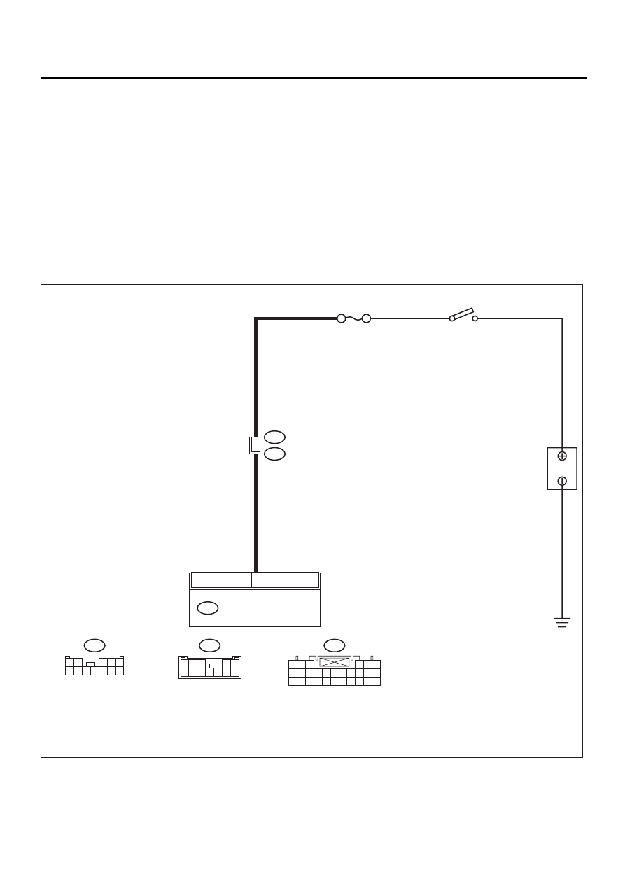
WIRING DIAGRAM:
AB-00296
5
11
AIRBAG CONTROL MODULE
AB6
B31
AB1
NO. 6
B
A
TTER
Y
IG SW
AB6
1 2 3
4 5 6
7 8 9 10 11 12 13 14 15 16 17
18 19 20 21 22 23 24 25 26 27 28
B31
1 2
3 4 5
6 7 8 9 10 11 12
AB1
1
2
3
4
5
6
7
8
9
10
11
12

AB-47
AIRBAG SYSTEM (DIAGNOSTICS)
DIAGNOSTIC CHART WITH DIAGNOSTIC TROUBLE CODE (DTC)
Step
Value
Yes
No
1
CHECK FUSE NO. 6 (IN JOINT BOX).
1) Confirm that the ignition switch is turned
OFF.
2) Remove No. 6 fuse (in joint box) and per-
form visual inspection.
Is fuse No. 6 blown?
Fuse No. 6 is not blown.
Replace fuse No.
6. If fuse No. 6 is
blown again,
repair the body
harness.
2
CHECK AIRBAG CONTROL MODULE.
1) Turn the ignition switch OFF, disconnect
the battery ground cable, and wait more
than 20 seconds.
2) Disconnect the connector (AB6) from air-
bag control module. <Ref. to AB-17, Airbag
Control Module.>
3) Connect the connector (1I) in test harness
I2 to connector (AB6).
4) Connect the battery ground cable, and turn
the ignition switch ON.
5) Measure the voltage between the connec-
tor (2I) in test harness I2 and the chassis
ground.
Connector & terminal
(2I) No. 6 (+) — Chassis ground (
−−−−
):
Does the measured value exceed the spec-
ified value?
10 V
Replace the airbag
control module.
<Ref. to AB-17,
Airbag Control
Module.>
3
CHECK AIRBAG MAIN HARNESS.
1) While checking control module, turn the
ignition switch OFF and disconnect the bat-
tery ground cable. Wait more than 20 sec-
onds before operation.
2) Disconnect the airbag connector (AB1)
from the body harness (B31).
3) Measure the voltage between the connec-
tor (B31) and the chassis ground.
Connector & terminal
(B31) No. 11 (+) — Chassis ground (
−−−−
):
Does the measured value exceed the spec-
ified value?
10 V
Replace the airbag
main harness.
<Ref. to AB-15,
Main Harness.>
Repair the body
harness.
AB-48
AIRBAG SYSTEM (DIAGNOSTICS)
DIAGNOSTIC CHART WITH DIAGNOSTIC TROUBLE CODE (DTC)
J: DTC 31
DIAGNOSIS:
• Front sub-sensor harness (RH) circuit is shorted.
• Front sub-sensor harness (RH) circuit is open.
• Front sub-sensor (RH) is faulty.
• Airbag control module is faulty.
CAUTION:
• Before diagnosing the airbag system, be sure to turn the ignition switch OFF, disconnect the
ground cable from the battery, and wait more than 20 seconds before starting to work.
• Before replacing the airbag module, roll connector, control module, and sensor, reconnect each
part and confirm that the warning light operates properly.
• When inspecting the airbag main harness, disconnect the driver's airbag module and passenger's
airbag module connectors for safety reasons.
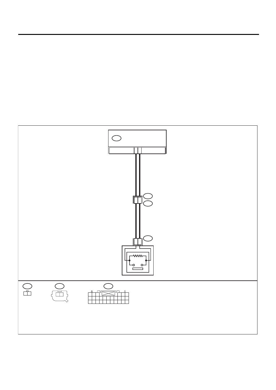
WIRING DIAGRAM:
AB-00297
20
9
FRONT SUB SENSOR RH
2
1
1
2
AIRBAG CONTROL MODULE
AB6
AB14
AB15
AB16
AB15
AB16
1 2
AB6
1 2 3
4 5 6
7 8 9 10 11 12 13 14 15 16 17
18 19 20 21 22 23 24 25 26 27 28
2
1

AB-49
AIRBAG SYSTEM (DIAGNOSTICS)
DIAGNOSTIC CHART WITH DIAGNOSTIC TROUBLE CODE (DTC)
Step
Value
Yes
No
1
CHECK FRONT SUB-SENSOR (RH) AND
FRONT SUB-SENSOR HARNESS (RH).
1) Turn the ignition switch OFF, disconnect
the battery ground cable, and wait more
than 20 seconds.
2) Disconnect the connector (AB6) from the
airbag control module , and connect the
connector (1I) in test harness I2. <Ref. to
AB-17, Airbag Control Module.>
3) Measure the resistance of the connector
(3I) in test harness I2.
Connector & terminal
(3I) No. 2 — No. 4:
Is the measured value within the specified
range?
750
Ω
— 1 K
Ω
2
CHECK FRONT SUB-SENSOR (RH) AND
FRONT SUB-SENSOR HARNESS (RH).
Measure the resistance between connector
(3I) in test harness I2 and the chassis ground.
Connector & terminal
(3I) No. 2 — Chassis ground:
(3I) No. 4 — Chassis ground:
Does the measured value exceed the specified
value?
1 M
Ω
Replace
the
airbag
control module.
<Ref. to AB-17,
Airbag Control
Module.>
3
CHECK AIRBAG MAIN HARNESS AND
FRONT SUB-SENSOR HARNESS (RH).
1) Disconnect connector (AB16) from the
front sub-sensor. <Ref. to AB-20, Front
Sub Sensor.>
2) Connect connector (IH) in test harness H to
connector (AB16).
3) Measure the resistance between connector
(3I) in test harness I2 and connector (3H) in
test harness H.
Connector & terminal
(3I) No. 2 — (3H) No. 5:
(3I) No. 4 — (3H) No. 6:
Is the measured value less than the speci-
fied value?
10
Ω
4
CHECK AIRBAG MAIN HARNESS AND
FRONT SUB-SENSOR HARNESS (RH).
Measure the resistance between connector
(3I) in test harness I2 and the chassis ground.
Connector & terminal
(3I) No. 2 — Chassis ground:
(3I) No. 4 — Chassis ground:
Does the measured value exceed the specified
value?
1 M
Ω
Нет комментариевНе стесняйтесь поделиться с нами вашим ценным мнением.
Текст