Subaru Legacy III (2000-2003 year). Service manual — part 355
EN(H6DO)-222
ENGINE (DIAGNOSTICS)
DIAGNOSTIC PROCEDURE WITH DIAGNOSTIC TROUBLE CODE (DTC)
AV:DTC P0340 — CAMSHAFT POSITION SENSOR “A” CIRCUIT (BANK 1 OR
SINGLE SENSOR) —
• DTC DETECTING CONDITION:
• Immediately at fault recognition
• TROUBLE SYMPTOM:
• Engine stalls.
• Failure of engine to start
CAUTION:
After repair or replacement of faulty parts, conduct Clear Memory Mode <Ref. to EN(H6DO)-54, OP-
ERATION, Clear Memory Mode.> and Inspection Mode <Ref. to EN(H6DO)-47, OPERATION, Inspec-
tion Mode.>.
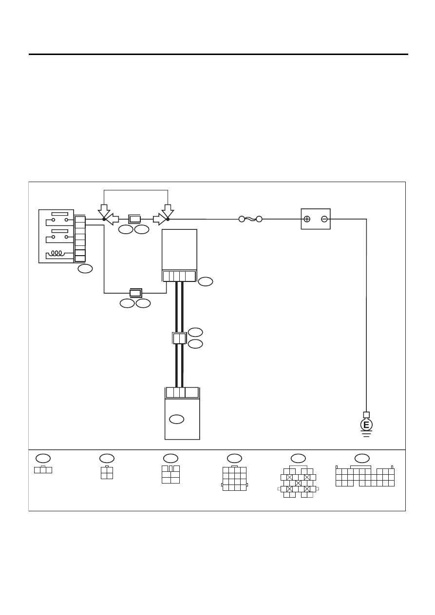
• WIRING DIAGRAM:
EN-01089
E15
3
2
1
10
2
8
10
1
10
B21
E2
B108
F46
B22
E3
E15
B135 ECM
CAMSHAFT
POSITION
SENSOR
SBF-5
B47
MAIN RELAY
1
2
3
5
4
6
1 2 3
LHD
RHD
LHD
RHD
B135
B21
1 2
5
6 7
8
13
14 15
16
9 10
11 12
3 4
17 18
19 20
5 6
7 8
2
1
9
4
3
10
24
22
23
25
11 12 13 14 15
26 27 28
16 17 18 19
20 21
F46
3 4
1 2
B47
3
4
1
2
5
6
B22
1 2 3 4
5 6 7 8
9 10 11 12
13 14 15 16

EN(H6DO)-223
ENGINE (DIAGNOSTICS)
DIAGNOSTIC PROCEDURE WITH DIAGNOSTIC TROUBLE CODE (DTC)
Step
Value
Yes
No
1
CHECK POWER SUPPLY TO CAMSHAFT
POSITION SENSOR.
1) Turn ignition switch to OFF.
2) Disconnect connector from camshaft posi-
tion sensor.
3) Measure voltage between camshaft posi-
tion sensor and engine ground.
Connector & terminal
(E15) No. 1 (+) — Engine ground (
−−−−
):
Does the measured value exceed the spec-
ified value?
10V Repair
ground
short circuit
between main
relay connector
and camshaft
position sensor
connector.
2
CHECK POWER SUPPLY TO CAMSHAFT
POSITION SENSOR.
1) Turn ignition switch to ON.
2) Measure voltage between camshaft posi-
tion sensor and engine ground.
Connector & terminal
(E15) No. 1 (+) — Engine ground (
−−−−
):
Does the measured value exceed the spec-
ified value?
10V
Repair open or
ground short cir-
cuit between main
relay connector
and camshaft
position sensor
connector.
3
CHECK HARNESS BETWEEN CAMSHAFT
POSITION SENSOR AND ECM.
1) Turn ignition switch to OFF.
2) Disconnect connector from ECM.
3) Measure resistance between camshaft
position sensor and ECM.
Connector & terminal
(E15) No. 2 — (B135) No. 1:
(E15) No. 3 — (B135) No. 10:
Is the measured value less than the speci-
fied value?
1
Ω
Repair open circuit
between camshaft
position sensor
and ECM.
4
CHECK HARNESS BETWEEN CAMSHAFT
POSITION SENSOR AND ECM.
Measure resistance between camshaft posi-
tion sensor and engine ground.
Connector & terminal
(E15) No. 2 — Engine ground:
(E15) No. 3 — Engine ground:
Does the measured value exceed the specified
value?
1 M
Ω
Repair ground
short circuit
between camshaft
position sensor
and ECM.
5
CHECK CONDITION OF CAMSHAFT POSI-
TION SENSOR.
Is the camshaft position sensor installation bolt
tightened securely?
Tightened securely.
Tighten camshaft
position sensor
installation bolt
securely.
6
CHECK CAMSHAFT POSITION SENSOR.
Check camshaft position sensor wave form.
<Ref. to EN(H6DO)-28, WAVEFORM, MEA-
SUREMENT, Engine Control Module (ECM) I/
O Signal.>
Is any abnormality found in waveform?
Normal waveform.
Replace camshaft
position sensor.
<Ref. to
FU(H6DO)-31,
Camshaft Position
Sensor.>
7
CHECK POOR CONTACT.
Check poor contact in ECM connector.
Is there poor contact in ECM connector?
There is poor contact.
Repair poor con-
tact in ECM con-
nector.
Replace ECM.
<Ref. to
FU(H6DO)-46,
Engine Control
Module.>

EN(H6DO)-224
ENGINE (DIAGNOSTICS)
DIAGNOSTIC PROCEDURE WITH DIAGNOSTIC TROUBLE CODE (DTC)
AW:DTC P0341 — CAMSHAFT POSITION SENSOR “A” CIRCUIT RANGE/PER-
FORMANCE (BANK 1 OR SINGLE SENSOR) —
• DTC DETECTING CONDITION:
• Tow consecutive driving cycles with fault
• TROUBLE SYMPTOM:
• Engine stalls.
• Failure of engine to start
CAUTION:
After repair or replacement of faulty parts, conduct Clear Memory Mode <Ref. to EN(H6DO)-54, OP-
ERATION, Clear Memory Mode.> and Inspection Mode <Ref. to EN(H6DO)-47, OPERATION, Inspec-
tion Mode.>.
• WIRING DIAGRAM:
EN-01089
E15
3
2
1
10
2
8
10
1
10
B21
E2
B108
F46
B22
E3
E15
B135 ECM
CAMSHAFT
POSITION
SENSOR
SBF-5
B47
MAIN RELAY
1
2
3
5
4
6
1 2 3
LHD
RHD
LHD
RHD
B135
B21
1 2
5
6 7
8
13
14 15
16
9 10
11 12
3 4
17 18
19 20
5 6
7 8
2
1
9
4
3
10
24
22
23
25
11 12 13 14 15
26 27 28
16 17 18 19
20 21
F46
3 4
1 2
B47
3
4
1
2
5
6
B22
1 2 3 4
5 6 7 8
9 10 11 12
13 14 15 16

EN(H6DO)-225
ENGINE (DIAGNOSTICS)
DIAGNOSTIC PROCEDURE WITH DIAGNOSTIC TROUBLE CODE (DTC)
Step
Value
Yes
No
1
CHECK ANY OTHER DTC ON DISPLAY.
Is any other DTC displayed?
Another DTC is displayed.
Inspect DTC
P0340 using “List
of Diagnostic
Trouble Code
(DTC)”. <Ref. to
EN(H6DO)-89, List
of Diagnostic
Trouble Code
(DTC).>
2
CHECK CONDITION OF CAMSHAFT POSI-
TION SENSOR.
Is the camshaft position sensor installation bolt
tightened securely?
Tightened securely.
Tighten camshaft
position sensor
installation bolt
securely.
3
CHECK CAMSHAFT SPROCKET.
Remove front chain cover. <Ref. to
ME(H6DO)-39, Front Chain Cover.>
Are camshaft sprocket teeth cracked or dam-
aged?
Cracked or damaged.
Replace camshaft
sprocket. <Ref. to
ME(H6DO)-46,
Camshaft
Sprocket.>
4
CHECK INSTALLATION CONDITION OF
TIMING CHAIN.
Turn crankshaft using ST, and align alignment
mark on camshaft sprocket with alignment
mark.
ST
18252AA000 CRANKSHAFT SOCKET
Is timing chain dislocated from its proper posi-
tion?
Dislocated from proper posi-
tion.
Repair installation
condition of timing
chain. <Ref. to
ME(H6DO)-41,
Timing Chain
Assembly.>
Replace camshaft
position sensor.
<Ref. to
FU(H6DO)-31,
Camshaft Position
Sensor.>
Нет комментариевНе стесняйтесь поделиться с нами вашим ценным мнением.
Текст