Subaru Legacy III (2000-2003 year). Service manual — part 463

EN(H4DOSTC)-22
ENGINE (DIAGNOSTICS)
ENGINE CONTROL MODULE (ECM) I/O SIGNAL
Pressure
sensor
Signal
B135
8
1.7 — 2.4
1.1 — 1.6
—
Power
supply
B135
9
5
5
GND (sen-
sor)
B135
19
0
0
Small light switch
B134
17
ON: 0
OFF: 10 — 13
ON: 0
OFF: 13 — 14
—
Blower fan switch
B134
9
ON: 0
OFF: 10 — 13
ON: 0
OFF: 13 — 14
—
Rear defogger switch
B134
3
ON: 0
OFF: 10 — 13
ON: 0
OFF: 13 — 14
—
Power steering oil pres-
sure switch
B135
24
10 — 13
ON: 0
OFF: 13 — 14
—
Front oxygen (A/F) sen-
sor signal (+)
B137
19
2.8 — 3.2
2.8 — 3.2
—
Front oxygen (A/F) sen-
sor signal (
−
)
B137
29
2.4 — 2.7
2.4 — 2.7
—
Front oxygen (A/F) sen-
sor shield
B137
18
0
0
—
SSM/GST communica-
tion line
B134
21
Less than 1
←→
More
than 4
Less than 1
←→
More
than 4
—
GND (sensors)
B135
19
0
0
—
GND (injectors)
B136
8
0
0
—
GND (ignition system)
B136
18
0
0
—
GND (power supply)
B136
17
0
0
—
B134
22
0
0
—
GND (control systems)
B134
7
0
0
—
B134
15
0
0
—
GND (oxygen sensor
heater 1)
B137
9
0
0
—
GND (oxygen sensor
heater 2)
B137
8
0
0
—
Differential pressure
sensor signal
B135
15
2
2
—
Relief valve control
solenoid valve 2 signal
B136
11
10 — 13
13 — 14
—
Relief valve control
solenoid valve 1 signal
B136
12
10 — 13
13 — 14
—
Exhaust valve control
solenoid valve (nega-
tive pressure) signal
B136
3
10 — 13
13 — 14
—
Exhaust valve control
solenoid valve (positive
pressure) signal
B136
1
10 — 13
13 — 14
—
Intake air valve control
solenoid valve signal
B137
12
10 — 13
13 — 14
—
Exhaust valve control
duty solenoid valve
B137
11
10 — 13
13 — 14
—
Content
Con-
nector
No.
Termi-
nal No.
Signal (V)
Note
Ignition SW ON
(Engine OFF)
Engine ON (Idling)

EN(H4DOSTC)-23
ENGINE (DIAGNOSTICS)
ENGINE CONDITION DATA
6. Engine Condition Data
A: ELECTRICAL SPECIFICATION
Measuring condition:
• After engine is warmed-up.
• Gear position is in neutral position.
• A/C is turned OFF.
• All accessory switches are turned OFF.
Content
Specified data
Engine load
1.6 — 2.9 (%): Idling
6.4 — 12.8 (%): 2,500 rpm racing
EN(H4DOSTC)-24
ENGINE (DIAGNOSTICS)
TRANSMISSION CONTROL MODULE (TCM) I/O SIGNAL
7. Transmission Control Module (TCM) I/O Signal
A: ELECTRICAL SPECIFICATION
<Ref. to AT-14, Transmission Control Module (TCM) I/O Signal.>
EN(H4DOSTC)-25
ENGINE (DIAGNOSTICS)
DATA LINK CONNECTOR
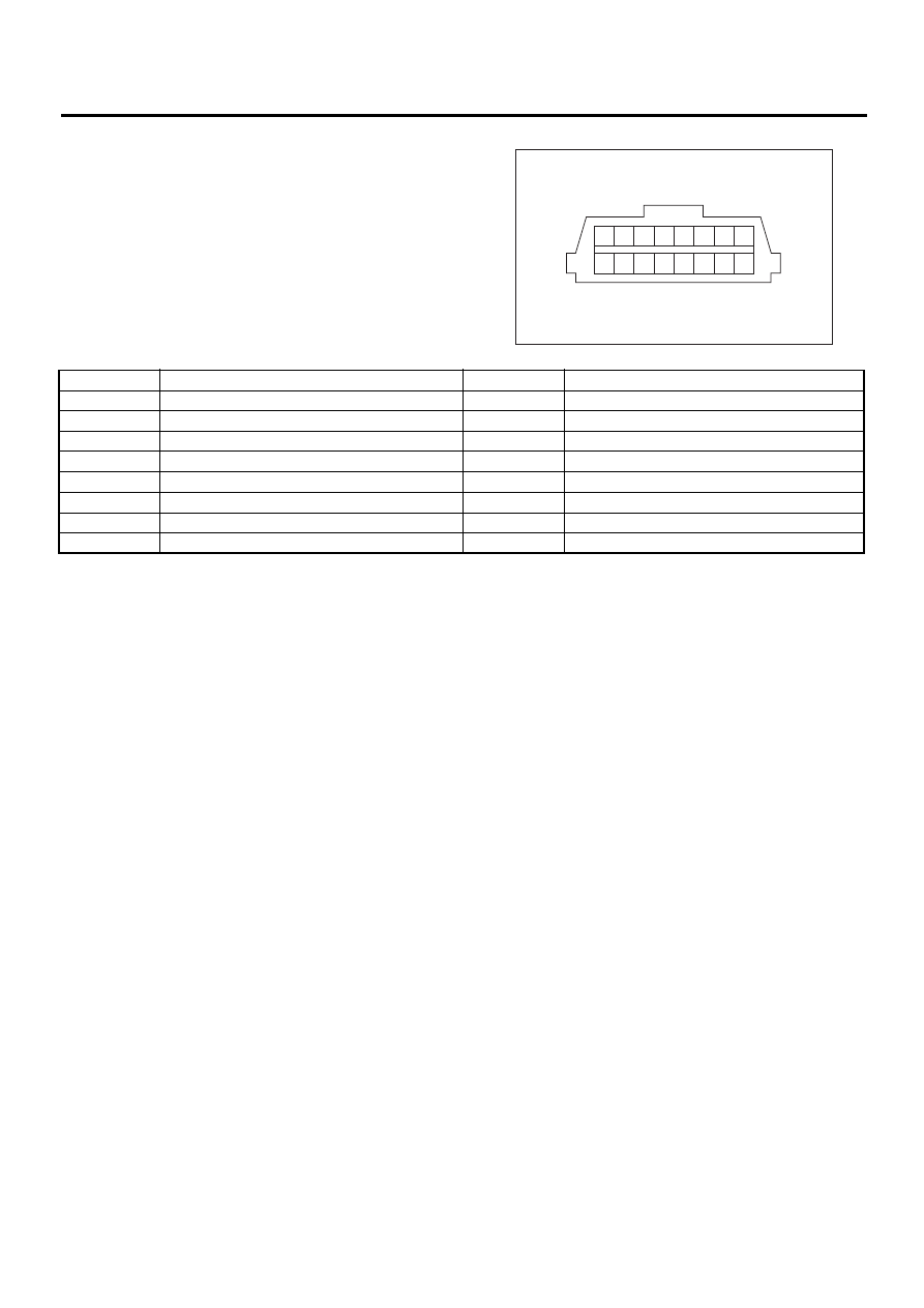
8. Data Link Connector
A: NOTE
1) This connector is used both for OBD-II general
scan tools and the Subaru Select Monitor.
2) Terminal No. 4 to No. 6 of the data link connector
is used for the Subaru Select Monitor signal.
CAUTION:
Do not connect any scan tools other than the
OBD-II general scan tools and Subaru Select
Monitor, because the circuit for the Subaru Se-
lect Monitor may be damaged.
EN-00037
12
11
10
9
13
15
14
16
3
2
1
7 8
4 5 6
Terminal No.
Contents
Terminal No.
Contents
1
Power supply
9
Blank
2
Blank
10
K line of ISO 9141 CARB
3
Blank
11
Blank
4
Blank
12
Ground
5
Blank
13
Ground
6
Flash write
14
Blank
7
Blank
15
Blank
8
Blank
16
Blank
Нет комментариевНе стесняйтесь поделиться с нами вашим ценным мнением.
Текст