Subaru Legacy III (2000-2003 year). Service manual — part 462
EN(H4DOSTC)-18
ENGINE (DIAGNOSTICS)
ELECTRICAL COMPONENTS LOCATION
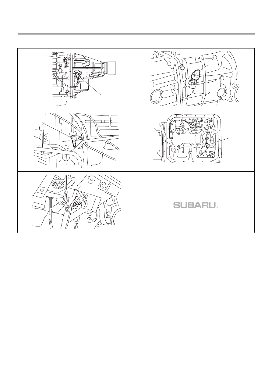
• SENSOR
(1) Rear vehicle speed sensor (for AT vehicles)
(2) Front vehicle speed sensor (for MT vehicles)
(3) Front vehicle speed sensor (for AT vehicles)
(4) Torque converter turbine speed sensor
(5) ATF temperature sensor (for AT vehicles)
(6) Brake light switch
EN-00881
( 1 )
( 3 )
EN-00882
( 2 )
EN-00883
( 4 )
EN-00884
( 5 )
EN-00885
( 6 )
EN(H4DOSTC)-19
ENGINE (DIAGNOSTICS)
ELECTRICAL COMPONENTS LOCATION
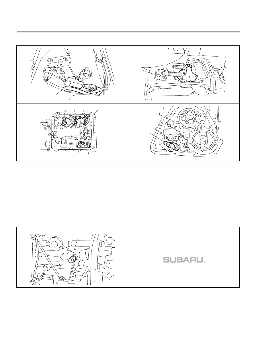
• SOLENOID VALVE AND SWITCH (AT VEHICLES)
(1) Dropping resistor
(2) Inhibitor switch
(3) Shift solenoid valve 1
(4) Shift solenoid valve 2
(5) Line pressure duty solenoid
(6) Lock-up duty solenoid
(7) Transfer duty solenoid
(8) 2-4 brake duty solenoid
(9) Low clutch timing solenoid valve
(10) 2-4 brake timing solenoid valve
• SOLENOID VALVE AND SWITCH (MT VEHICLES)
(1) Neutral position switch
EN-00886
( 1 )
EN-00887
( 2 )
EN-00888
( 3 )
( 4 )
( 5 )
( 6 )
( 8 )
( 9 )
(10)
EN-00889
( 7 )
EN-00996
( 1 )
EN(H4DOSTC)-20
ENGINE (DIAGNOSTICS)
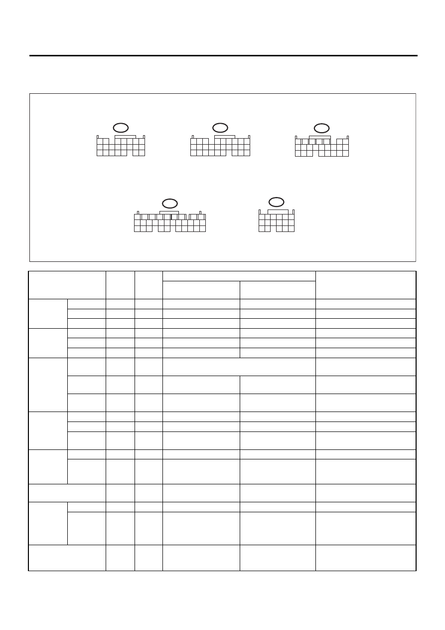
ENGINE CONTROL MODULE (ECM) I/O SIGNAL
5. Engine Control Module (ECM) I/O Signal
A: ELECTRICAL SPECIFICATION
Content
Con-
nector
No.
Termi-
nal No.
Signal (V)
Note
Ignition SW ON
(Engine OFF)
Engine ON (Idling)
Crank-
shaft posi-
tion sensor
Signal (+)
B135
2
0
−
7 — +7
Sensor output waveform
Signal (
−
)
B135
11
0
0
—
Shield
B135
21
0
0
—
Camshaft
position
sensor
Signal (+)
B135
1
0
−
7 — +7
Sensor output waveform
Signal (
−
)
B135
10
0
0
—
Shield
B135
21
0
0
—
Throttle
position
sensor
Signal
B135
7
Fully closed: 0.2 — 1.0
Fully opened: 4.2 — 4.7
—
Power
supply
B135
9
5
5
—
GND (sen-
sor)
B135
19
0
0
—
Rear oxy-
gen sen-
sor
Signal
B135
17
0
0 — 0.9
—
Shield
B135
26
0
0
—
GND (sen-
sor)
B135
19
0
0
—
Front oxy-
gen (A/F)
sensor
heater
Signal 1
B137
4
0 — 1.0
0 — 1.0
—
Signal 2
B137
5
0 — 1.0
0 — 1.0
—
Rear oxygen sensor
heater signal
B136
13
0 — 1.0
0 — 1.0
—
Engine
coolant
tempera-
ture sen-
sor
Signal
B135
18
1.0 — 1.4
1.0 — 1.4
After warm-up the engine.
GND (sen-
sor)
B135
19
0
0
After warm-up the engine.
Vehicle speed signal
B134
1
0 or 5
0 or 5
“5” and “0” are repeatedly dis-
played when the vehicle is
driven.
EN-00997
B134
To
1
2
3
4
10
11
12
19
20
21
13
5
6
14
15
7
8
9
16
17
18
22
B135
To
5
6
7
8
2 1
9
4 3
10
24
22
23
25
11
12
13
14
15
26
27
28
16
17
18
19
20
21
To
B136
1
2
7
8
9
5
6
3
4
10
11
12
19
20
21
13
14
15
16
17
18
22
23
24
To
B137
1
2
7
8
9
5
6
3
4
10
11
12
19
20
21
29
30
31
13
14
15
16
17
27
28
18
22
23
24
25
26
B84
To
1
2
3
8
9
10
4
11
12
13
14
15
16
5
6
7
17
EN(H4DOSTC)-21
ENGINE (DIAGNOSTICS)
ENGINE CONTROL MODULE (ECM) I/O SIGNAL
Mass air
flow sen-
sor
Signal
B84
13
—
0.3 — 4.5
—
Shield
B84
8
0
0
—
GND
B84
7
0
0
—
Intake air temperature
sensor signal
B135
27
—
—
—
Wastegate control sole-
noid valve
B137
24
10 — 13
13 — 14
—
Starter switch
B134
16
0
0
Cranking: 8 — 14
A/C switch
B134
6
ON: 10 — 13
OFF: 0
ON: 13 — 14
OFF: 0
—
Ignition switch
B134
14
10 — 13
13 — 14
—
Neutral position switch
(MT)
B134
8
ON: 12
±
0.5
OFF: 0
Switch is ON when gear is in
neutral position.
Neutral position switch
(AT)
B134
8
ON: 0
OFF: 12
±
0.5
Switch is ON when shift is in “N”
or “P” position.
Test mode connector
B134
5
5
5
When connected: 0
Knock
sensor
Signal
B135
4
2.8
2.8
—
Shield
B135
22
0
0
—
Back-up power supply
B137
10
10 — 13
13 — 14
Ignition switch “OFF”: 10 — 13
Control unit power sup-
ply
B137
2
10 — 13
13 — 14
—
B137
3
10 — 13
13 — 14
—
Sensor power supply
B135
9
5
5
—
Line end check
B134
10
0
0
—
Ignition
control
#1
B136
24
0
13 — 14
Waveform
#2
B136
23
0
13 — 14
Waveform
#3
B136
22
0
13 — 14
Waveform
#4
B136
21
0
13 — 14
Waveform
Fuel injec-
tor
#1
B137
1
10 — 13
1 — 14
Waveform
#2
B136
6
10 — 13
1 — 14
Waveform
#3
B136
5
10 — 13
1 — 14
Waveform
#4
B136
4
10 — 13
1 — 14
Waveform
Idle air
control
solenoid
valve
Signal
B136
10
0 or 13 — 14
0 or 13 — 14
Waveform
Fuel pump
controller
Signal 1
B134
13
—
—
—
Signal 2
B136
16
—
—
—
A/C relay control
B137
27
ON: 0.5, or less
OFF: 10 — 13
ON: 0.5, or less
OFF: 13 — 14
—
Radiator fan relay 1
control
B137
17
ON: 0.5, or less
OFF: 10 — 13
ON: 0.5, or less
OFF: 13 — 14
—
Radiator fan relay 2
control
B137
28
ON: 0.5, or less
OFF: 10 — 13
ON: 0.5, or less
OFF: 13 — 14
With A/C vehicles only
Malfunction indicator
lamp
B137
15
—
—
Light “ON”: 1, or less
Light “OFF”: 10 — 14
Engine speed output
B136
9
—
0 — 13, or more
Waveform
Torque control signal 1
B134
19
5
5
—
Torque control signal 2
B134
18
5
5
—
Torque control cut sig-
nal
B136
14
8
8
—
Purge control solenoid
valve
B137
16
ON: 1, or less
OFF: 10 — 13
ON: 1, or less
OFF: 13 — 14
—
Content
Con-
nector
No.
Termi-
nal No.
Signal (V)
Note
Ignition SW ON
(Engine OFF)
Engine ON (Idling)
Нет комментариевНе стесняйтесь поделиться с нами вашим ценным мнением.
Текст