Subaru Legacy III (2000-2003 year). Service manual — part 668
DI-26
DIFFERENTIALS
REAR DIFFERENTIAL FOR T-TYPE
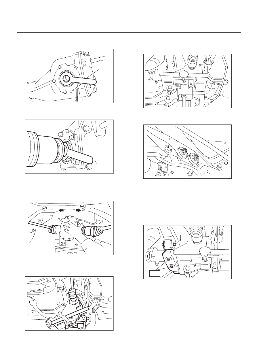
3) Install ST to rear differential.
ST
28099PA090
OIL SEAL PROTECTOR
4) Insert the spline shaft until the spline portion is
inside the side oil seal.
5) Remove ST from rear differential.
ST
28099PA090
OIL SEAL PROTECTOR
6) Completely insert axle shaft into rear differential
by pressing rear differential.
7) Adjust transmission jack as required so rear dif-
ferential stud bolt is properly inserted into rear
crossmember bushing.
8) After rear differential stud bolt has been inserted
into rear crossmember bushing, raise transmission
jack to make jack rear differential level.
9) Temporarily tighten rear crossmember self-lock-
ing nuts.
10) Remove band from rear differential. Raise rear
differential just enough to move transmission jack
away from it.
11) Install rear differential front member.
Tightening torque:
T1: 65 N·m (6.6 kgf-m, 48 ft-lb)
T2: 110 N·m (11.2 kgf-m, 81 ft-lb)
DI-00279
ST
DI-00280
DI-00281
DI-00282
DI-00283
DI-00269
DI-00284
T2
T1
DI-27
DIFFERENTIALS
REAR DIFFERENTIAL FOR T-TYPE
12) Tighten self-locking nuts.
Tightening torque:
70 N·m (7.1 kgf-m, 51 ft-lb)
13) Tighten protector nut.
Tightening torque:
65 N·m (6.6 kgf-m, 48.0 ft-lb)
14) Take down transmission jack.
15) Install propeller shaft.
<Ref. to DS-15, INSTALLATION, Propeller Shaft.>
16) Install heat shield cover.
17) Install rear exhaust pipe and muffler.
18) After installing rear differential carrier on vehi-
cle, remove filler plug and replenish gear oil up to
upper level mark.
Oil capacity:
0.8
2
(0.8 US qt, 0.7 Imp qt)
19) Tighten filler plug.
NOTE:
Apply fluid packing to plug.
Fluid packing:
THREE BOND 1105 (Part No.: 04403010) or
equivalent
Tightening torque:
49.0 N·m (5.0 kgf-m, 36.2 ft-lb)
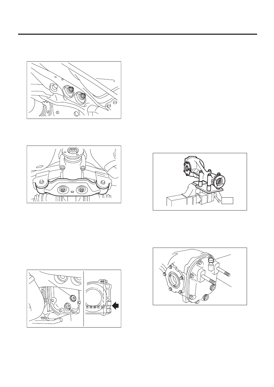
C: DISASSEMBLY
To detect real cause of trouble, inspect the follow-
ing items before disassembling.
• Tooth contact of crown gear and pinion, and
backlash
• Runout of crown gear at its back surface
• Turning resistance of drive pinion
1) Set ST on vise and install the differential assem-
bly to ST.
ST
398217700
ATTACHMENT
2) Drain gear oil by removing plug.
3) Remove the air breather cap.
NOTE:
Do not attempt to replace the air breather cap un-
less necessary.
(A) Filler plug
(B) Drain plug
DI-00269
DI-00272
DI-00285
( A )
( B )
(A) Air breather cap
(B) Rear cover
DI-00061
ST
DI-00062
( A )
( B )
DI-28
DIFFERENTIALS
REAR DIFFERENTIAL FOR T-TYPE
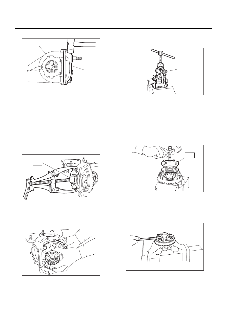
4) Remove rear cover by loosening retaining bolts.
5) Make right and left side bearing retainers in or-
der to identify them at reassembly. Remove side
bearing retainer attaching bolts, set ST to differen-
tial case, and extract right and left side bearing re-
tainers with a puller.
NOTE:
Each shim, which is installed to adjust the side
bearing preload, should be kept together with its
mating retainer.
ST
398457700
ATTACHMENT
6) Pull out differential case assembly from differen-
tial carrier.
CAUTION:
Be careful not to hit the teeth against the case.
7) Remove O-ring from side bearing retainer.
8) Remove oil seal from side bearing retainer.
9) When replacing side bearing, pull bearing cup
from side bearing retainer using ST.
ST
398527700
PULLER ASSY
10) Extract bearing cone with ST.
NOTE:
• Do not attempt to disassemble the parts unless
necessary.
• Set puller so that its claws catch the edge of the
bearing cone.
• Never mix up the right and left hand bearing rac-
es and cones.
ST
399527700
PULLER SET
11) Remove crown gear by loosening crown gear
bolts.
NOTE:
For rear differential case with LSD, differential case
should not be disassembled.
(A) Rear cover
(B) Differential carrier
DI-00063
( A )
( B )
DI-00064
ST
DI-00065
DI-00066
ST
DI-00067
ST
DI-00068
DI-29
DIFFERENTIALS
REAR DIFFERENTIAL FOR T-TYPE
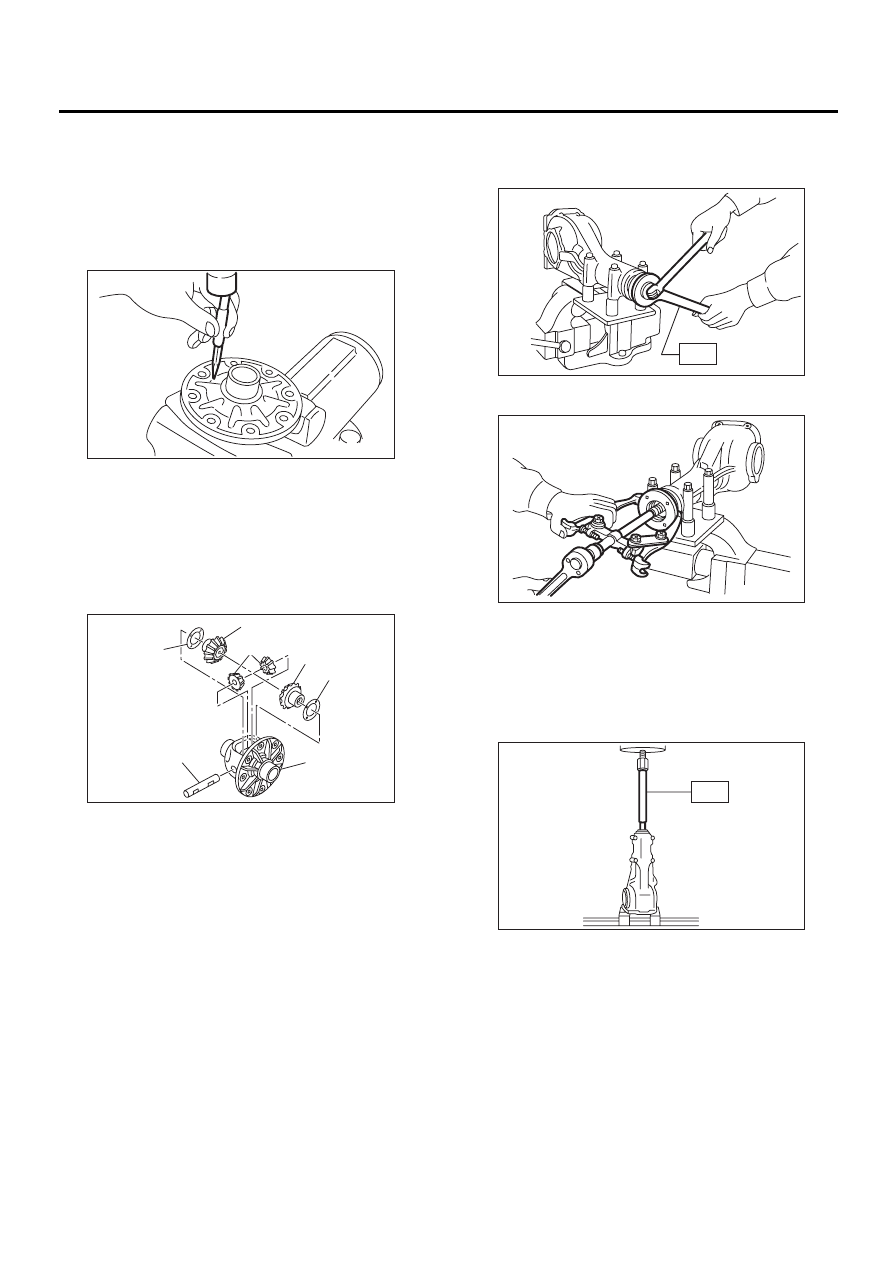
12) Drive out pinion shaft lock pin from crown gear
side. (Without LSD)
NOTE:
The lock pin is staked at the pin hole end on the dif-
ferential carrier; do not drive it out forcibly before
unstaking it.
ST
899904100
STRAIGHT PIN REMOVER
13) Draw out pinion mate shaft and remove pinion
mate gears, side gears and thrust washers. (With-
out LSD)
NOTE:
The gears as well as thrust washers should be
marked or kept separated left and right, and front
and rear.
14) Hold companion flange with ST and remove
drive pinion nut.
ST
498427200
FLANGE WRENCH
15) Extract the companion flange with a puller.
16) Press the end of drive pinion shaft and extract it
together with rear bearing cone, preload adjusting
spacer and washer.
NOTE:
Hold the drive pinion so as not to drop it.
ST
398467700
DRIFT
(A) Side gear
(B) Pinion mate gear
(C) Thrust washer
(D) Differential case
(E) Pinion mate shaft
DI-00237
DI-00238
( A )
( A )
( B )
( C )
( C )
( D )
( E )
DI-00071
ST
DI-00072
ST
DI-00073
Нет комментариевНе стесняйтесь поделиться с нами вашим ценным мнением.
Текст