Subaru Legacy III (2000-2003 year). Service manual — part 719
ABS-94
ABS (DIAGNOSTICS)
DIAGNOSTICS CHART WITH SUBARU SELECT MONITOR
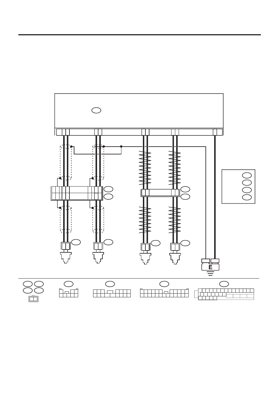
J: DTC 28 REAR LEFT ABNORMAL ABS SENSOR SIGNAL
DIAGNOSIS:
• Faulty ABS sensor signal (noise, irregular signal, etc.)
• Faulty harness/connector
TROUBLE SYMPTOM:
• ABS does not operate.
WIRING DIAGRAM:
ABS00309
R73
R72
F49
FRONT
ABS
SENSOR LH
FRONT
ABS
SENSOR RH
ABS CONTROL MODULE AND HYDRAULIC CONTROL UNIT
F49
2
1
1 2 3 4 5 6 7 8 9 10 11 12 13 14 15
16 17 18 19 20 21 22
27 28 29 30 31
23
24
25
26
9
10
11
12
1
2
1
2
1
4
7
8
1
2
5
6
14
15
1
2
23
F55
R49
B15
B6
R73
R72
REAR
ABS
SENSOR LH
REAR
ABS
SENSOR RH
B6
B15
F55
15
16
14
12
13
17
8
9
13
11
12
10
F45
1
*
2
*
RHD
LHD
1
*
2
*
: LHD
RHD
: LHD
RHD B100
B62
F2
F45
1 2 3
4 5 6 7
8 9 10 11
12 13 14 15 16
1
2 3
4 5 6 7 8
F2
3 4
1 2
8 9 10 11
12 13 14 15 16 17 18 19 20 21 22 23 24
5 6
7

ABS-95
ABS (DIAGNOSTICS)
DIAGNOSTICS CHART WITH SUBARU SELECT MONITOR
Step
Value
Yes
No
1
CHECK OUTPUT OF ABS SENSOR USING
SELECT MONITOR.
1) Select “Current data display & Save” on the
select monitor.
2) Read the ABS sensor output corresponding
to the faulty system in the select monitor
data display mode.
Does the speed indicated on the display
change in response to the speedometer
reading during acceleration/deceleration
when the steering wheel is in the straight-
ahead position?
Change as same.
2
CHECK POOR CONTACT IN CONNECTORS.
Turn ignition switch to OFF.
Is there poor contact in connectors between
ABSCM&H/U and ABS sensor?
There is no poor contact.
Repair connector.
3
CHECK SOURCES OF SIGNAL NOISE.
Is the car telephone or the wireless transmitter
properly installed?
Installed properly.
Properly install the
car telephone or
the wireless trans-
mitter.
4
CHECK SOURCES OF SIGNAL NOISE.
Are noise sources (such as an antenna)
installed near the sensor harness?
Noise source is not installed
near the sensor harness.
Install the noise
sources apart from
the sensor har-
ness.
5
CHECK SHIELD CIRCUIT.
1) Turn ignition switch to OFF.
2) Connect all connectors.
3) Measure resistance between shield con-
nector and chassis ground.
Connector & terminal
DTC 22 / LHD: (F45) No. 13 — Chassis
ground:
RHD: (F2) No. 14 — Chassis ground:
DTC 24 / LHD: (F45) No. 10 — Chassis
ground:
RHD: (F2) No. 17 — Chassis ground:
Is the measured value less than the speci-
fied value?
NOTE:
For the DTC 26 and 28:
Go to step 6.
0.5
Ω
Repair shield har-
ness.
6
CHECK ABSCM&H/U.
1) Connect all connectors.
2) Erase the memory.
3) Perform inspection mode.
4) Read out the DTC.
Is the same DTC still being output?
Same DTC is not indicated.
Replace
ABSCM&H/U.
<Ref. to ABS-6,
ABS Control Mod-
ule and Hydraulic
Control Unit
(ABSCM&H/U).>
7
CHECK ANY OTHER DTC APPEARANCE.
Are other DTC being output?
Other DTC is not indicated.
A temporary noise
interference.
Proceed with the
diagnosis corre-
sponding to the
DTC.
8
CHECK INSTALLATION OF ABS SENSOR.
Are the ABS sensor installation bolts tightened
with the specified torque?
33
±
10 N·m (3.4
±
1.0 kgf-m,
25
±
7 ft-lb)
Tighten ABS sen-
sor installation
bolts securely.

ABS-96
ABS (DIAGNOSTICS)
DIAGNOSTICS CHART WITH SUBARU SELECT MONITOR
9
CHECK ABS SENSOR GAP.
Measure tone wheel to ABS sensor piece gap
over entire perimeter of the wheel.
Is the measured value within the specified
range?
Front wheel 0.3 — 0.8 mm
(0.012 — 0.031 in) and Rear
wheel 0.44 — 0.94 mm
(0.0173 — 0.0370 in)
Adjust the gap.
NOTE:
Adjust the gap us-
ing spacer (Part
No. 26755AA000).
If spacers cannot
correct the gap, re-
place worn sensor
or worn tone
wheel.
10
PREPARE OSCILLOSCOPE.
Is an oscilloscope available?
Available.
11
CHECK ABS SENSOR SIGNAL.
1) Lift-up the vehicle.
2) Turn ignition switch to OFF.
3) Connect the oscilloscope to the connector.
4) Turn ignition switch to ON.
5) Rotate wheels and measure voltage at
specified frequency. <Ref. to ABS-15,
WAVEFORM, Control Module I/O Signal.>
NOTE:
When this inspection is completed, the AB-
SCM&H/U sometimes stores the trouble code
29.
Connector & terminal
DTC 22 / LHD: (F45) No. 11 (+) — No. 12
(
−−−−
):
RHD: (F2) No. 12 (+) — No. 13 (
−−−−
):
DTC 24/LHD: (F45) No. 8 (+) — No. 9 (
−−−−
):
RHD: (F2) No. 15 (+) — No. 16 (
−−−−
):
DTC 26 / (F55) No. 5 (+) — No. 6 (
−−−−
):
DTC 28 / (F55) No. 1 (+) — No. 4 (
−−−−
):
Is the measured value same with the speci-
fied value?
Oscilloscope pattern is as
shown in figure.
12
CHECK CONTAMINATION OF ABS SENSOR
OR TONE WHEEL.
Remove disc rotor from hub in accordance
with diagnostic trouble code.
Is the ABS sensor piece or the tone wheel con-
taminated by mud or other foreign matter?
ABS sensor piece or the tone
wheel is not contaminated.
Thoroughly
remove dirt or
other foreign mat-
ter.
13
CHECK DAMAGE OF ABS SENSOR OR
TONE WHEEL.
Are there broken or damaged in the ABS sen-
sor piece or the tone wheel?
No broken or damaged.
Replace ABS sen-
sor or tone wheel.
Front: <Ref. to
ABS-12, Front
ABS Sensor.>
Rear: <Ref. to
ABS-15, Rear
ABS Sensor.>
and Front: <Ref.
to ABS-19, Front
Tone Wheel.>
Rear: <Ref. to
ABS-20, Rear
Tone Wheel.>
Step
Value
Yes
No

ABS-97
ABS (DIAGNOSTICS)
DIAGNOSTICS CHART WITH SUBARU SELECT MONITOR
14
CHECK TONE WHEEL RUNOUT.
Measure tone wheel runout.
Is the measured value less than the specified
value?
0.05 mm (0.0020 in)
Replace tone
wheel. Front:
<Ref. to ABS-19,
Front Tone
Wheel.> Rear:
<Ref. to ABS-20,
Rear Tone
Wheel.>
15
CHECK RESISTANCE OF ABS SENSOR.
1) Turn ignition switch to OFF.
2) Disconnect connector from ABS sensor.
3) Measure resistance between ABS sensor
connector terminals.
Terminal
Front RH No. 1 — No. 2:
Front LH No. 1 — No. 2:
Rear RH No. 1 — No. 2:
Rear LH No. 1 — No. 2:
Is the measured value within the specified
range?
1 - 1.5 k
Ω
Replace ABS sen-
sor. Front: <Ref.
to ABS-12, Front
ABS Sensor.>
Rear: <Ref. to
ABS-15, Rear
ABS Sensor.>
16
CHECK GROUND SHORT OF ABS SENSOR.
Measure resistance between ABS sensor and
chassis ground.
Terminal
Front RH No. 1 — Chassis ground:
Front LH No. 1 — Chassis ground:
Rear RH No. 1 — Chassis ground:
Rear LH No. 1 — Chassis ground:
Does the measured value exceed the specified
value?
1 M
Ω
Replace ABS sen-
sor. Front: <Ref.
to ABS-12, Front
ABS Sensor.>
Rear: <Ref. to
ABS-15, Rear
ABS Sensor.>
17
CHECK HARNESS/CONNECTOR BETWEEN
ABSCM&H/U AND ABS SENSOR.
1) Connect connector to ABS sensor.
2) Disconnect connector from ABSCM&H/U.
3) Measure resistance at ABSCM&H/U con-
nector terminals.
Connector & terminal
DTC 22 / (F49) No. 11 — No. 12:
DTC 24 / (F49) No. 9 — No. 10:
DTC 26 / (F49) No. 14 — No. 15:
DTC 28 / (F49) No. 7 — No. 8:
Is the measured value within the specified
range?
1 - 1.5 k
Ω
Repair harness/
connector
between
ABSCM&H/U and
ABS sensor.
18
CHECK GROUND SHORT OF HARNESS.
Measure resistance between ABSCM&H/U
connector and chassis ground.
Connector & terminal
DTC 22 / (F49) No. 11 — Chassis
ground:
DTC 24 / (F49) No. 9 — Chassis ground:
DTC 26 / (F49) No. 14 — Chassis
ground:
DTC 28 / (F49) No. 7 — Chassis ground:
Does the measured value exceed the specified
value?
1 M
Ω
Repair harness/
connector
between
ABSCM&H/U and
ABS sensor.
Step
Value
Yes
No
Нет комментариевНе стесняйтесь поделиться с нами вашим ценным мнением.
Текст