Subaru Legacy III (2000-2003 year). Service manual — part 717
ABS-86
ABS (DIAGNOSTICS)
DIAGNOSTICS CHART WITH SUBARU SELECT MONITOR
C: DTC 21 OPEN OR SHORT CIRCUIT IN FRONT RIGHT ABS SENSOR CIRCUIT
NOTE:
For the diagnostic procedure, refer to DTC 27. <Ref. to ABS-88, DTC 27 OPEN OR SHORT CIRCUIT IN
REAR LEFT ABS SENSOR CIRCUIT, Diagnostics Chart with Subaru Select Monitor.>
D: DTC 23 OPEN OR SHORT CIRCUIT IN FRONT LEFT ABS SENSOR CIRCUIT
NOTE:
For the diagnostic procedure, refer to DTC 27. <Ref. to ABS-88, DTC 27 OPEN OR SHORT CIRCUIT IN
REAR LEFT ABS SENSOR CIRCUIT, Diagnostics Chart with Subaru Select Monitor.>
E: DTC 25 OPEN OR SHORT CIRCUIT IN REAR RIGHT ABS SENSOR CIRCUIT
NOTE:
For the diagnostic procedure, refer to DTC 27. <Ref. to ABS-88, DTC 27 OPEN OR SHORT CIRCUIT IN
REAR LEFT ABS SENSOR CIRCUIT, Diagnostics Chart with Subaru Select Monitor.>
ABS-87
ABS (DIAGNOSTICS)
DIAGNOSTICS CHART WITH SUBARU SELECT MONITOR
MEMO:
ABS-88
ABS (DIAGNOSTICS)
DIAGNOSTICS CHART WITH SUBARU SELECT MONITOR
F: DTC 27 OPEN OR SHORT CIRCUIT IN REAR LEFT ABS SENSOR CIRCUIT
DIAGNOSIS:
• Faulty ABS sensor (Broken wire, input voltage too high)
• Faulty harness connector
TROUBLE SYMPTOM:
• ABS does not operate.
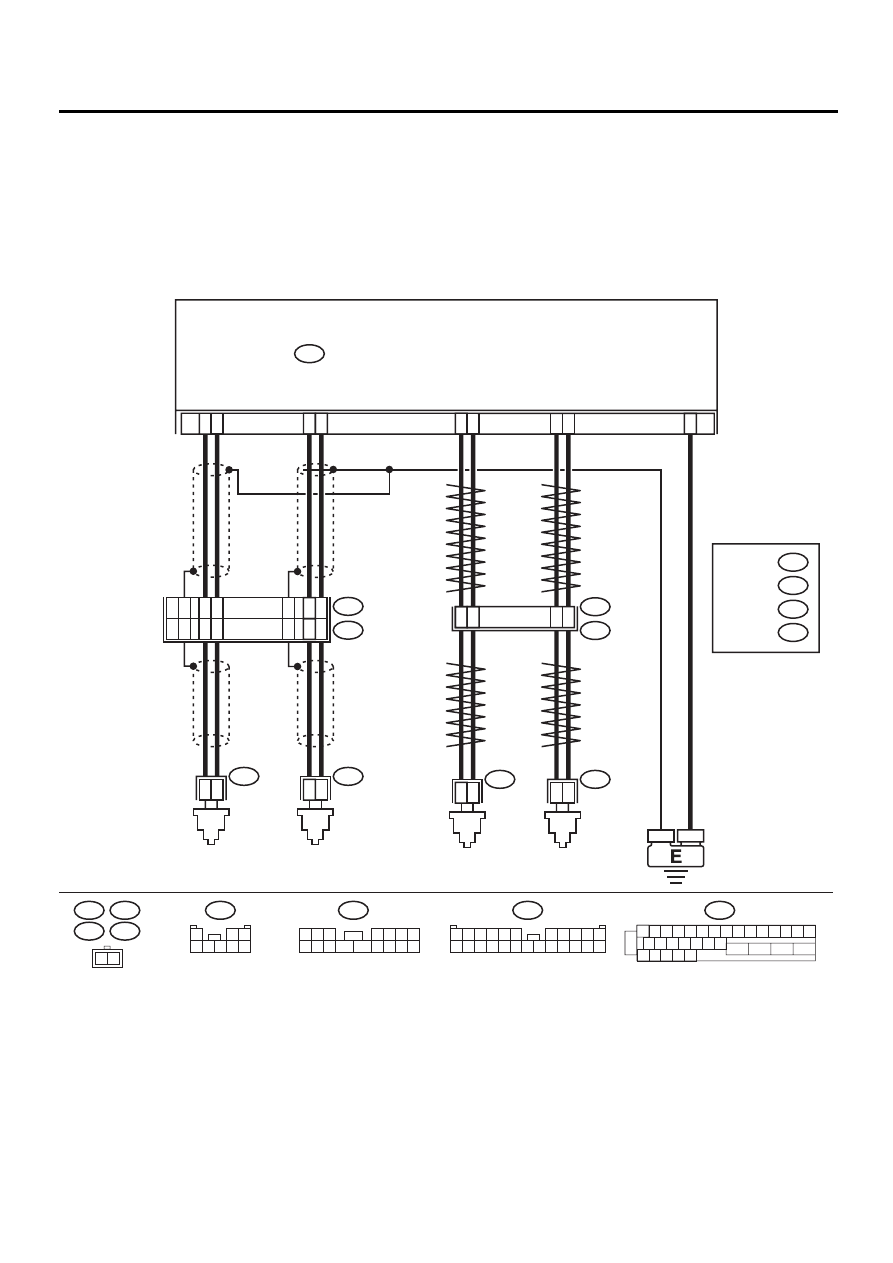
WIRING DIAGRAM:
ABS00309
R73
R72
F49
FRONT
ABS
SENSOR LH
FRONT
ABS
SENSOR RH
ABS CONTROL MODULE AND HYDRAULIC CONTROL UNIT
F49
2
1
1 2 3 4 5 6 7 8 9 10 11 12 13 14 15
16 17 18 19 20 21 22
27 28 29 30 31
23
24
25
26
9
10
11
12
1
2
1
2
1
4
7
8
1
2
5
6
14
15
1
2
23
F55
R49
B15
B6
R73
R72
REAR
ABS
SENSOR LH
REAR
ABS
SENSOR RH
B6
B15
F55
15
16
14
12
13
17
8
9
13
11
12
10
F45
1
*
2
*
RHD
LHD
1
*
2
*
: LHD
RHD
: LHD
RHD B100
B62
F2
F45
1 2 3
4 5 6 7
8 9 10 11
12 13 14 15 16
1
2 3
4 5 6 7 8
F2
3 4
1 2
8 9 10 11
12 13 14 15 16 17 18 19 20 21 22 23 24
5 6
7

ABS-89
ABS (DIAGNOSTICS)
DIAGNOSTICS CHART WITH SUBARU SELECT MONITOR
Step
Value
Yes
No
1
CHECK OUTPUT OF ABS SENSOR USING
SELECT MONITOR.
1) Select “Current data display & Save” on the
select monitor.
2) Read the ABS sensor output corresponding
to the faulty system in the select monitor
data display mode.
Does the speed indicated on the display
change in response to the speedometer
reading during acceleration/deceleration
when the steering wheel is in the straight-
ahead position?
Change as same.
2
CHECK INSTALLATION OF ABS SENSOR.
Are the ABS sensor installation bolts tightened
with the specified torque?
33
±
10 N·m (3.4
±
1.0 kgf-m,
25
±
7 ft-lb)
Tighten ABS sen-
sor installation
bolts securely.
3
CHECK ABS SENSOR GAP.
Measure tone wheel to ABS sensor piece gap
over entire perimeter of the wheel.
Is the measured value within the specified
range?
Front wheel 0.3 — 0.8 mm
(0.012 — 0.031 in) and Rear
wheel 0.44 — 0.94 mm
(0.0173 — 0.0370 in)
Adjust the gap.
NOTE:
Adjust the gap us-
ing spacers (Part
No. 26755AA000).
If spacers cannot
correct the gap, re-
place worn sensor
or worn tone
wheel.
4
CHECK TONE WHEEL RUNOUT.
Measure tone wheel runout.
Is the measured value less than the specified
value?
0.05 mm (0.0020 in)
Replace tone
wheel. Front:
<Ref. to ABS-19,
Front Tone
Wheel.> Rear:
<Ref. to ABS-20,
Rear Tone
Wheel.>
5
CHECK POOR CONTACT IN CONNECTORS.
Turn ignition switch to OFF.
Is there poor contact in connectors between
ABSCM&H/U and ABS sensor?
There is no poor contact.
Repair connector.
6
CHECK ABSCM&H/U.
1) Connect all connectors.
2) Erase the memory.
3) Perform inspection mode.
4) Read out the DTC.
Is the same DTC still being output?
Same DTC is not indicated.
Replace
ABSCM&H/U.
<Ref. to ABS-6,
ABS Control Mod-
ule and Hydraulic
Control Unit
(ABSCM&H/U).>
7
CHECK ANY OTHER DTC APPEARANCE.
Are other DTC being output?
Other DTC is not indicated.
A temporary poor
contact.
NOTE:
Check harness
and connectors
between AB-
SCM&H/U and
ABS sensor.
Proceed with the
diagnosis corre-
sponding to the
DTC.
Нет комментариевНе стесняйтесь поделиться с нами вашим ценным мнением.
Текст