Subaru Legacy III (2000-2003 year). Service manual — part 95
SC(H4SO)-14
STARTING/CHARGING SYSTEMS
GENERATOR
3. Generator
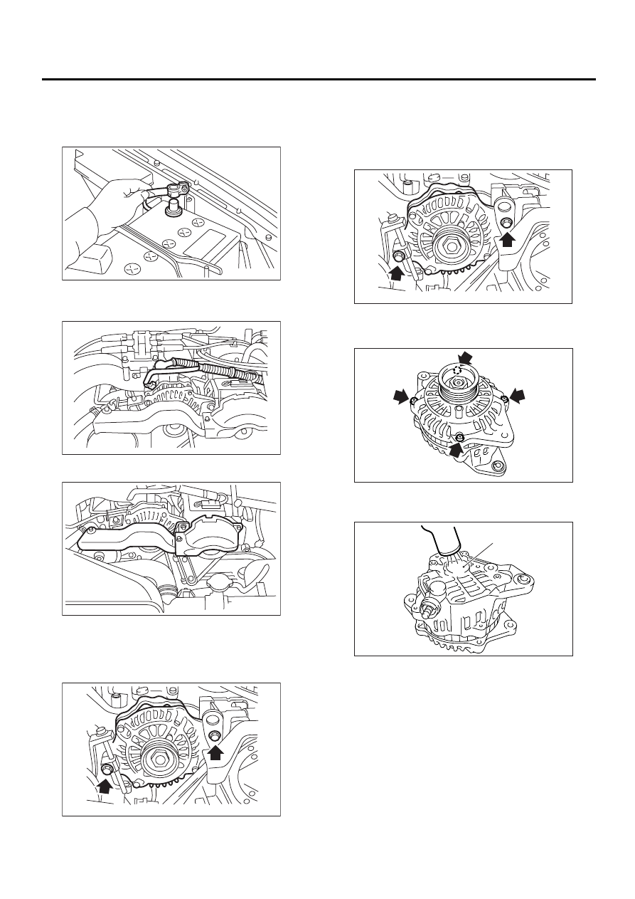
A: REMOVAL
1) Disconnect the ground cable from battery.
2) Disconnect the connector and terminal from
generator.
3) Remove the V-belt cover.
4) Remove the front side V-belt.
<Ref. to ME(H4SO)-41, REMOVAL, V-belt.>
5) Remove the bolts which install generator onto
bracket.
B: INSTALLATION
Install in the reverse order of removal.
CAUTION:
Check and adjust the V-belt tension. <Ref. to
ME(H4SO)-42, INSPECTION, V-belt.>
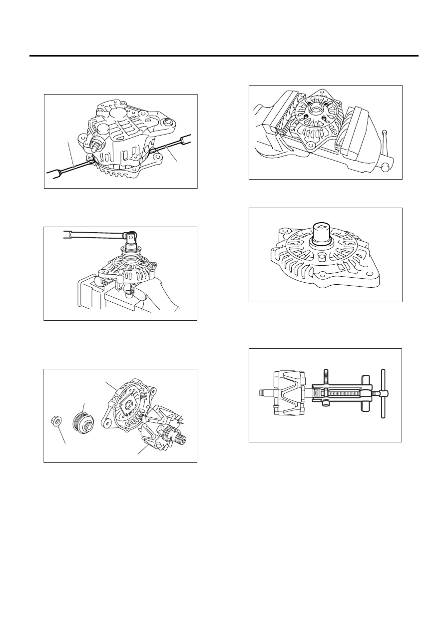
C: DISASSEMBLY
1) Remove the four through-bolts.
2) Heat the portion (A) of rear cover to 50
°
C
(122
°
F) with heater drier.
FU-00009
SC-00029
SC-00031
SC-00032
SC-00032
SC-00078
SC-00079
(A)
SC(H4SO)-15
STARTING/CHARGING SYSTEMS
GENERATOR
3) Then insert the tip of a flat tip screwdriver into the
gap between stator core and front cover. Pry them
apart to disassemble.
4) Hold the rotor with a vise and remove pulley nut.
CAUTION:
When holding the rotor with vise, insert alumi-
num plates or wood pieces on the contact sur-
faces of vise to prevent rotor from damage.
5) Remove the ball bearing as follows.
(1) Remove the bolt, and then remove the bear-
ing retainer.
(2) Firmly install an appropriate tool (such as a
fit socket wrench) to bearing inner race.
(3) Push the ball bearing off the front cover us-
ing a press.
6) Remove the bearing from rotor using a bearing
puller.
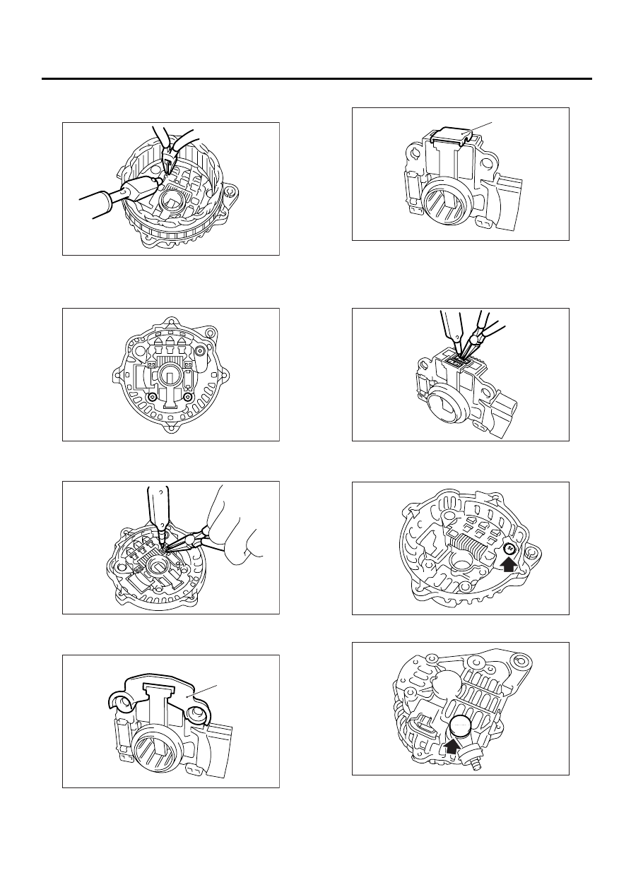
7) Unsolder connection between rectifier and stator
coil to remove the stator coil.
CAUTION:
Do not allow the 180 — 270 W solding bit to con-
tact the terminals for more than 5 seconds at a
(A) Screwdriver
(A) Front cover
(B) Pulley
(C) Nut
(D) Rotor
SC-00080
(A)
(A)
SC-00035
( A )
( B )
( C )
( D )
SC-00036
SC-00081
SC-00082
SC-00046
SC(H4SO)-16
STARTING/CHARGING SYSTEMS
GENERATOR
time because the rectifier cannot withstand
heat very well.
8) Remove the IC regulator as follows.
(1) Remove the screws which secure IC regula-
tor to rear cover.
(2) Unsolder the connection between IC regula-
tor and rectifier to remove the IC regulator.
9) Remove the brush as follows.
(1) Remove cover A.
(2) Remove the cover B.
(3) Separate the brush from connection to re-
move.
10) Remove the rectifier as follows.
(1) Remove the bolts which secure the rectifier.
(2) Remove the cover of terminal B.
(A) Cover A
SC-00083
SC-00084
SC-00085
SC-00086
(A)
(A) Cover B
SC-00087
(A)
SC-00088
SC-00089
SC-00090
SC(H4SO)-17
STARTING/CHARGING SYSTEMS
GENERATOR
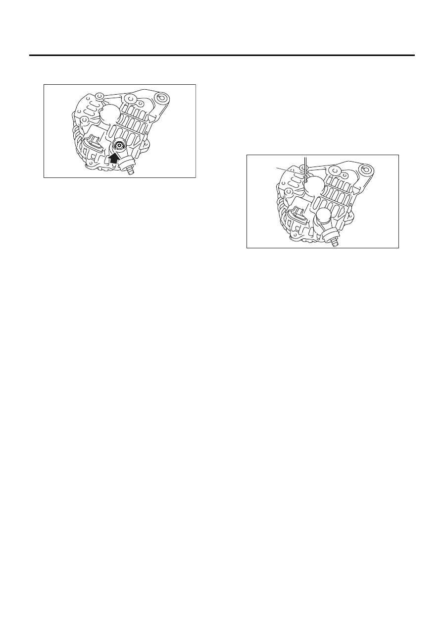
(3) Remove the nut of terminal B, and then re-
move the rectifier.
D: ASSEMBLY
To assemble, reverse order of disassembly.
1) Pulling up brush
Before assembling, press the brush down into
brush holder, and then fix them in that position by
passing a [1 mm (0.04 in) dia. length 4 to 5 cm (1.6
to 2.0 in)] wire through the hole shown in the figure.
CAUTION:
Be sure to remove the wire after reassembly.
2) Install the ball bearing.
(1) Set the ball bearing on the front cover, and
then securely install an appropriate tool (such as
a fit socket wrench) to the bearing outer race.
(2) Press the ball bearing into the specified po-
sition using a press.
(3) Install the bearing retainer.
3) Press the bearing (rear side) into the rotor shaft
using a press to install.
4) Heat the bearing box in rear cover [50 to 60
°
C
(122 to 140
°
F)], and then press the rear bearing
into rear cover.
CAUTION:
Grease should not be applied to rear bearing.
Remove the oil completely if it is found on bear-
ing box.
5) After reassembly, turn the pulley by hand to
check that rotor turns smoothly.
SC-00091
(A) Wire
SC-00092
(A)
Нет комментариевНе стесняйтесь поделиться с нами вашим ценным мнением.
Текст