Subaru Legacy III (2000-2003 year). Service manual — part 93
SC(H4SO)-6
STARTING/CHARGING SYSTEMS
STARTER
2. Starter
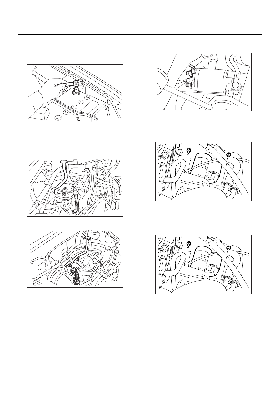
A: REMOVAL
1) Disconnect the ground cable from battery.
2) Remove the air cleaner case.
<Ref. to IN(H4SO)-6, REMOVAL, Air Cleaner
Case.>
3) Remove the air cleaner case stay.
• MT vehicles
• AT vehicles
4) Disconnect the connector and terminal from
starter.
5) Remove the starter from transmission.
B: INSTALLATION
Install in the reverse order of removal.
Tightening torque:
50 N·m (5.1 kgf-m, 37 ft-lb)
FU-00009
SC-00004
SC-00005
(A) Terminal
(B) Connector
SC-00006
( A )
( B )
SC-00007
SC-00007
SC(H4SO)-7
STARTING/CHARGING SYSTEMS
STARTER
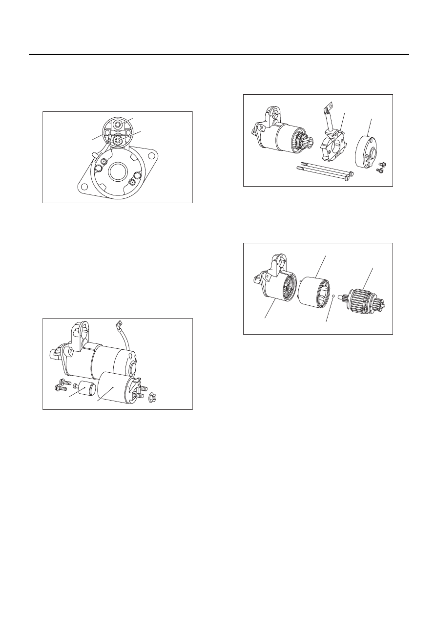
C: DISASSEMBLY
1. STARTER ASSEMBLY
1) Loosen nut which holds terminal M of switch as-
sembly, and disconnect connector.
2) Remove bolts which hold switch assembly, and
remove switch assembly, plunger and plunger
spring from starter as a unit.
NOTE:
Be careful because pinion gap adjustment washer
may sometimes be used on the mounting surface
of switch assembly.
3) Remove both through-bolts and brush holder
screws, and detach rear bracket and brush holder.
NOTE:
Before removal, confirm the attachment locations
of brush holder and rear bracket.
4) Remove armature and yoke from the front brack-
et.
(A) Terminal M
(B) Terminal B
(C) Terminal S
(A) Switch ASSY
(B) Plunger
SC-00148
( A )
( B )
( C )
SC-00149
( A )
( B )
(A) Brush holder
(B) Rear bracket
(A) Armature
(B) Ball
(C) Yoke
(D) Front bracket
SC-00150
( A )
( B )
SC-00151
( A )
( B )
( C )
( D )
SC(H4SO)-8
STARTING/CHARGING SYSTEMS
STARTER
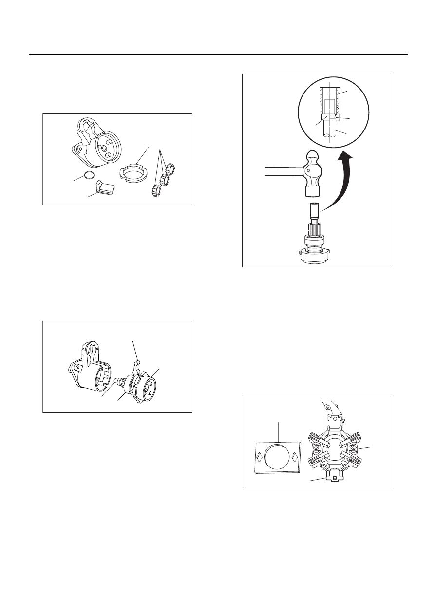
5) Remove packing A, three planetary gears, pack-
ing B and plate.
NOTE:
Before removal, confirm the inserting location of
packing A.
6) Remove shaft assembly and overrunning clutch
as a unit.
NOTE:
Before removal, confirm the following:
• Lever direction
• Internal gear assembly position
7) Remove overrunning clutch from shaft assembly
as follows:
(1) Remove stopper from ring by lightly tapping
the stopper with an appropriate tool (such as a
socket).
(2) Remove ring, stopper and clutch from shaft.
2. BRUSH HOLDER
Slightly open the metal fitting holding the insulating
plate to the brush holder. Remove the insulating
plate.
NOTE:
The brush and spring can be easily removed from
the brush holder at this time.
(A) Packing A
(B) Planetary gear
(C) Plate
(D) Packing B
(A) Lever
(B) Shaft ASSY
(C) Overrunning clutch
(D) Internal gear ASSY
SC-00152
( D )
( C )
( B )
( A )
SC-00153
( A )
( B )
( C )
( D )
(A) Socket wrench
(B) Ring
(C) Shaft
(D) Stopper
(A) Brush holder
(B) Insulating plate
(C) Metal fitting
SC-00014
( A )
( B )
( C )
( D )
SC-00154
( A )
( B )
( C )
SC(H4SO)-9
STARTING/CHARGING SYSTEMS
STARTER
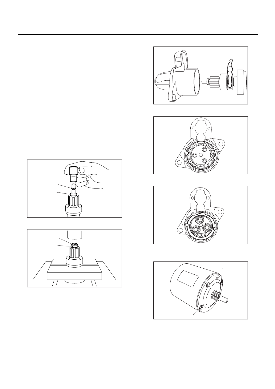
D: ASSEMBLY
Assemble in the reverse order of disassembly. Do
the following:
NOTE:
When assembling, apply grease to the following
parts.
• Front and rear bracket sleeve bearing
• Armature shaft gear
• Outer periphery of plunger
• Mating surface of plunger and lever
• Gear shaft splines
• Mating surface of lever and clutch
• Ball at the armature shaft end
• Internal and planetary gears
1) Install overrunning clutch to shaft assembly.
2) Install stopper to shaft assembly in the following
order.
(1) Insert the ring into the shaft groove by lightly
tapping it with an appropriate tool (such as a fit
socket wrench).
(2) Install the stopper to ring using a press.
3) When installing shaft assembly to front bracket,
be careful of the following.
• Lever direction
• Internal gear position
• Packing position
4) When installing yoke to the front bracket, match
bolt hole.
(A) Ring
(B) Stopper
SC-00067
(B)
(A)
SC-00068
(A)
(B)
(A) Bolt hole
SC-00155
SC-00156
SC-00157
SC-00158
( A )
( A )
Нет комментариевНе стесняйтесь поделиться с нами вашим ценным мнением.
Текст