Subaru Tribeca (2014 year). Instruction — part 7
or wiring of the SRS airbag system.
This includes following modifica-
tions.
. Installation of custom steering
wheels
. Attachment of additional trim
materials to the dashboard
. Installation of custom seats
. Replacement of seat fabric or
leather
. Installation of additional fabric or
leather on the front seat
. Attachment of a hands-free mi-
crophone or any other accessory
to a front pillar, a center pillar, a
rear pillar, the windshield, a side
window, an assist grip, or any
other cabin surface that would be
near a deploying SRS curtain
airbag.
. Installation of additional electri-
cal/electronic equipment such as
a mobile two-way radio on or
near the SRS airbag system
components and/or wiring is not
advisable. This could interfere
with proper operation of the
SRS airbag system.
CAUTION
Do not perform any of the following
modifications. Such modifications
can interfere with proper operation
of the SRS airbag system.
. Attachment of any equipment
(bush bar, winches, snow plow,
skid plate, etc.) other than genu-
ine SUBARU accessory parts.
. Modification of the suspension
system or front end structure.
. Installation of a tire of different
size and construction from the
tires specified on the vehicle
placard attached to the driver’s
door pillar or specified for indivi-
dual vehicle models in this Own-
er’s Instruction.
. Attachment of any equipment
(side steps or side sill protectors,
etc.) other than genuine SUBARU
accessory parts to the side body.
Always consult your SUBARU dealer if
you want to install any accessory parts on
your vehicle.
Seat, seatbelt and SRS airbags
1-73
— — — — — — — — — — — — — — — — — — — — — — — — — — — — — — — — — — — — — — — —
— — — — — — — — — — — — — — — — — — — — — — — — — — — — — — — — — — — — — — — —
— — — — — — — — — — — — — — — — — — — — — — — — — — — — — — — — — — — — — — — —
— — — — — — — — — — — — — — — — — — — — — — — — — — — — — — — — — — — — — — — —
— — — — — — — — — — — — — — — — — — — — — — — — — — — — — — — — — — — — — — — —
— — — — — — — — — — — — — — — — — — — — — — — — — — — — — — — — — — — — — — — —
— — — — — — — — — — — — — — — — — — — — — — — — — — — — — — — — — — — — — — — —
— — — — — — — — — — — — — — — — — — — — — — — — — — — — — — — — — — — — — — — —
— — — — — — — — — — — — — — — — — — — — — — — — — — — — — — — — — — — — — — — —
— — — — — — — — — — — — — — — — — — — — — — — — — — — — — — — — — — — — — — — —
— — — — — — — — — — — — — — — — — — — — — — — — — — — — — — — — — — — — — — — —
— — — — — — — — — — — — — — — — — — — — — — — — — — — — — — — — — — — — — — — —
— — — — — — — — — — — — — — — — — — — — — — — — — — — — — — — — — — — — — — — —
Keys . . . . . . . . . . . . . . . . . .
2-2
Key number plate. . . . . . . . . . . .
2-2
Immobilizer . . . . . . . . . . . . . . ..
2-3
Security ID plate. . . . . . . . . . . . ..
2-3
Security indicator light . . . . . . . . . .
2-4
Key replacement . . . . . . . . . . . . .
2-4
Door locks . . . . . . . . . . . . . . ...
2-5
Locking and unlocking from the outside . . . ..
2-5
Locking and unlocking from the inside . . . .
2-5
Battery drainage prevention function . . . . ...
2-6
Power door locking switches. . . . . . . .
2-7
Key lock-in prevention function . . . . . . ...
2-8
Remote keyless entry system . . . . . . .
2-8
Locking the doors . . . . . . . . . . . ...
2-9
Unlocking the doors . . . . . . . . . . ... 2-10
Unlocking the rear gate . . . . . . . . . .. 2-10
Illuminated entry . . . . . . . . . . . . 2-10
Vehicle finder function. . . . . . . . . . 2-10
Sounding a panic alarm. . . . . . . . . ..
2-11
Selecting audible signal operation . . . . . ..
2-11
Replacing the battery . . . . . . . . . . .
2-11
Replacing lost transmitters . . . . . . . .
2-12
Alarm system . . . . . . . . . . . . . .
2-16
System operation. . . . . . . . . . . ...
2-16
Activating and deactivating the alarm system . .
2-16
If you have accidentally triggered the alarm
system . . . . . . . . . . . . . . .
2-17
Arming the system . . . . . . . . . . .
2-17
Disarming the system . . . . . . . . . .
2-18
Valet mode . . . . . . . . . . . . . .
2-18
Passive arming. . . . . . . . . . . . ..
2-19
Tripped sensor identification . . . . . . . ..
2-20
Shock sensors (dealer option). . . . . . .
2-20
Child safety locks . . . . . . . . . . . ..
2-21
Windows. . . . . . . . . . . . . . . .
2-21
Power windows . . . . . . . . . . . . .
2-21
Rear gate . . . . . . . . . . . . . . .
2-24
Moonroof (if equipped). . . . . . . . . ..
2-25
Tilt function . . . . . . . . . . . . . ...
2-26
Sliding function . . . . . . . . . . . . .
2-26
Anti-entrapment function. . . . . . . . .
2-26
Sun shade . . . . . . . . . . . . . . .
2-27
Keys and doors
2
2-2
Keys and doors
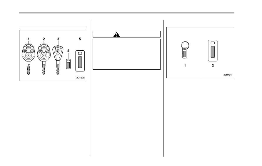
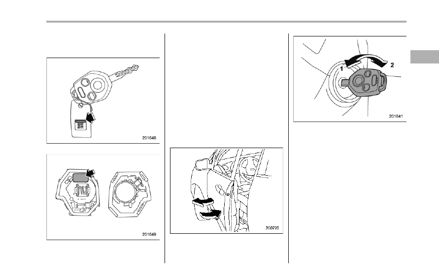
Keys
1)
Master key
2)
Submaster key
3)
Valet key
4)
Key number plate
5)
Security ID plate
Three types of keys are provided for your
vehicle.
Master key, submaster key and valet key.
The master key and submaster key fit all
locks on your vehicle.
. Ignition switch
. Driver’s door
. Glove box
The valet key fits only the ignition switch
and door locks. You can keep the glove
box locked when you leave your vehicle
and valet key at a parking facility.
CAUTION
Do not attach a large key holder or
key case to either key. If it bangs
against your knees while you are
driving, it could turn the ignition
switch from the “ON” position to the
“Acc” or “LOCK” position, thereby
stopping the engine.
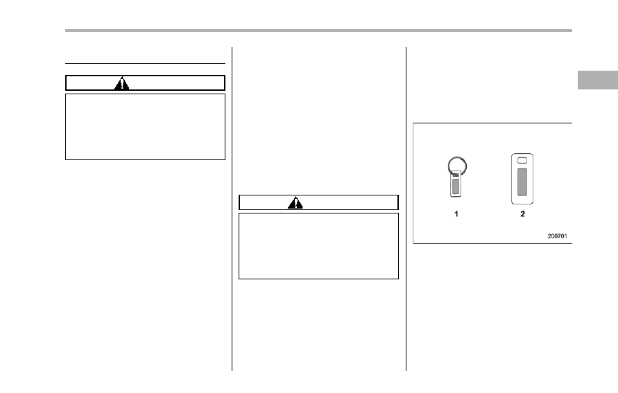
& Key number plate
1)
Key number plate
2)
Security ID plate
The key number is stamped on the key
number plate attached to the key set.
Write down the key number and keep it in
another safe place, not in the vehicle. This
number is needed to make a replacement
key if you lose your key or lock it inside the
vehicle.
For information on making replacement
keys for models with the immobilizer
system, refer to “Security ID plate” F2-3.
Immobilizer
CAUTION
FCC WARNING
Changes or modifications not ex-
pressly approved by the party re-
sponsible for compliance could void
the user’s authority to operate the
equipment.
The immobilizer system is designed to
prevent an unauthorized person from
starting the engine. Only keys registered
with your vehicle’s immobilizer system can
be used to operate your vehicle. Even if
an unregistered key fits into the ignition
switch and can be turned to the “START”
position, the engine will automatically stop
after several seconds.
Each immobilizer key contains a trans-
ponder in which the key’s ID code is
stored. When a key is inserted into the
ignition switch and turned to the “ON”
position, the transponder transmits the
key’s ID code to the immobilizer system’s
receiver. If the transmitted ID code
matches the ID code registered in the
immobilizer system, the system allows the
engine to be started. Since the ID code is
transmitted and acted upon almost in-
stantly, the immobilizer system does not
impede normal starting of the engine.
If the engine does not start, pull out the
key once before trying again. Refer to
“Ignition switch” F3-3.
This device complies with Part 15 of
the FCC Rules and RSS-Gen of IC
Rules. Operation is subject to the
following two conditions: (1) this de-
vice may not cause harmful interfer-
ence, and (2) this device must accept
any interference received, including
interference that may cause undesired
operation.
CAUTION
. Do not place the key under direct
sunlight or anywhere it may
become hot.
. Do not get the key wet. If the key
gets wet, wipe it dry with a cloth
immediately.
NOTE
To protect your vehicle from theft,
please pay close attention to the fol-
lowing security precautions.
. Never leave your vehicle unattended
with its keys inside.
. Before leaving your vehicle, close all
windows and lock the doors and rear
gate.
. Do not leave spare keys or any
record of your key number in the
vehicle.
& Security ID plate
1)
Key number plate
2)
Security ID plate
The security ID is stamped on the security
ID plate attached to the key set. Write
down the security ID and keep it in
another safe place, not in the vehicle.
This number is needed to make a replace-
ment key if you lose your key or lock it
inside the vehicle.
This number is also needed for replace-
ment or repair of the engine control unit,
Keys and doors
2-3
– CONTINUED –
2-4
Keys and doors
integrated unit, and combination meter.
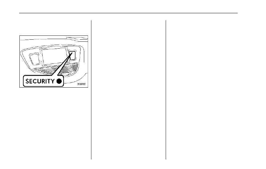
& Security indicator light
The security indicator light deters potential
thieves by indicating that the vehicle is
equipped with an immobilizer system. It
begins flashing approximately 60 seconds
after the ignition switch is turned from the
“ON” position to the “Acc” or “LOCK”
position or immediately after the key is
pulled out.
If the security indicator light does not flash,
the immobilizer system may be malfunc-
tioning. If this occurs, contact your
SUBARU dealer as soon as possible.
In case an unauthorized key is used (e.g.
an imitation key), the security indicator
light illuminates.
NOTE
Even if the security indicator light
flashes irregularly or its fuse blows
(the light does not flash if its fuse is
blown), the immobilizer system will
function normally.
& Key replacement
Your key number plate and security ID
plate will be required if you ever need a
replacement key made. Any new key must
be registered for use with your vehicle’s
immobilizer system before it can be used.
Up to four keys can be registered for use
with one vehicle.
For security, all the keys registered with
your vehicle’s immobilizer system will
have their ID codes erased and re-
registered when a new key is made.
Therefore, all of your vehicle’s keys must
be presented when a new key is regis-
tered. Any key that is not re-registered
when a new key is made cannot be used
after the other keys are re-registered. For
information on replacement keys and on
the registration of keys with your immo-
bilizer system, contact your SUBARU
dealer.
NOTE
A vehicle that is equipped with the
remote engine start system as a dealer
option can register up to three keys for
use with one vehicle.
Door locks
& Locking and unlocking from
the outside
To lock the driver’s door from the outside
with the key, turn the key toward the front.
To unlock the door, turn the key toward the
rear.
Lift the outside door handle to open an
unlocked door.
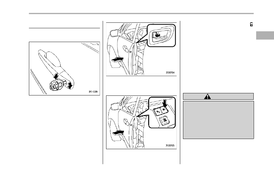
Locking without the key
To lock the door from the outside without
the key, rotate the lock lever rearward and
then close the door.
Locking without the key
To lock the door from the outside using the
power door locking switch, push the “ ”
sides of the switch and then close the
door. In this case, all closed doors and the
rear gate are locked at the same time.
Always make sure that all doors and the
rear gate are locked before leaving your
vehicle.
NOTE
Make sure that you do not leave the key
inside the vehicle before locking the
doors from the outside without the key.
& Locking and unlocking from
the inside
WARNING
Keep all doors locked when you
drive, especially when small chil-
dren are in your vehicle.
Along with the proper use of seat-
belts and child restraints, locking
the doors reduces the chance of
being thrown out of the vehicle in an
accident.
Keys and doors
2-5
– CONTINUED –
2-6
Keys and doors
It also helps prevent passengers
from falling out if a door is acciden-
tally opened, and intruders from
unexpectedly opening doors and
entering your vehicle.
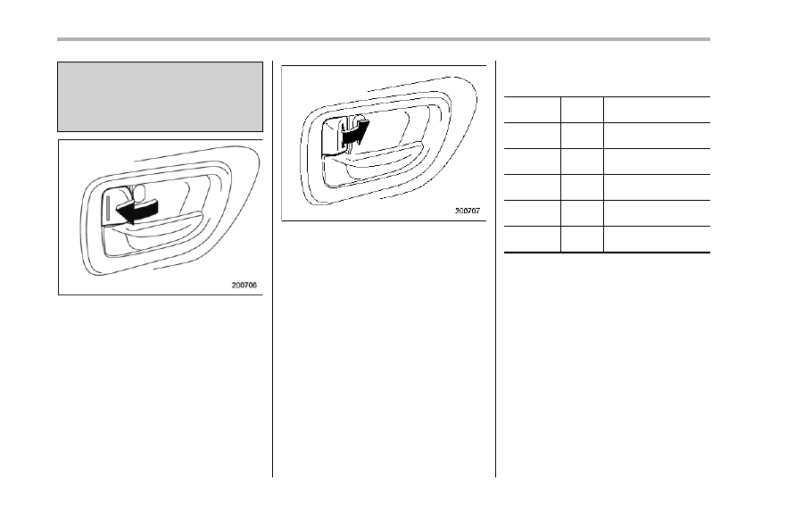
To lock the door from the inside, rotate the
lock lever rearward.
To unlock the door from the inside, rotate
the lock lever forward.
The red mark on the lock lever appears
when the door is unlocked.
Pull the inside door handle to open an
unlocked door.
Always make sure that all doors and the
rear gate are closed and locked before
starting to drive.
& Battery drainage prevention
function
If any of the doors or the rear gate is not
completely closed, the interior lights will
remain illuminated as a result. However,
several lights are automatically turned off
by the battery drainage prevention func-
tion to prevent the battery from dischar-
ging. The following interior lights are
affected by this function.
Item
Switch
position
Automatically turning
off
Map lights
OFF
Approximately 30
seconds later
Dome light
DOOR
Approximately 10
minutes later
Ignition
switch light
—
Approximately 10
minutes later
Door step
lights
—
None*
Cargo area
light
DOOR
None*
*: Door step lights and the cargo area light are
not affected by the battery drainage prevention
function, so the lights do not turn off automa-
tically. To turn off the lights, it is necessary that
each door and the rear gate are completely
closed.
The operational/non-operational setting of
this function can be changed by a
SUBARU dealer. Contact your SUBARU
dealer to change the setting.
NOTE
. The factory setting (default setting)
for this function is set as “operational”.
. When leaving the vehicle, please
make sure that all doors and the rear
gate are completely closed.
. The battery drainage prevention
function does not operate while the
key is in the ignition switch.
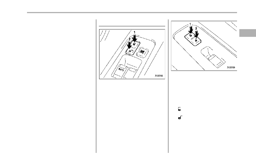
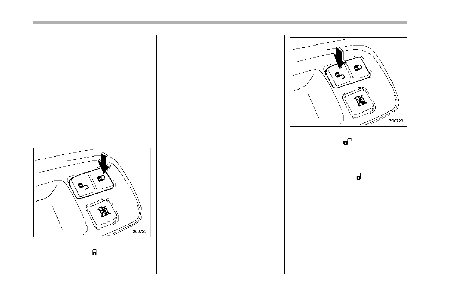
Power door locking switches
Driver’s switch
1)
Lock
2)
Unlock
Front passenger’s switch
1)
Lock
2)
Unlock
All doors and the rear gate can be locked
and unlocked by the power door locking
switches located at the driver’s side and
the front passenger’s side doors.
To lock all doors and the rear gate, push
the “ ” side of the switch.
To unlock all doors and the rear gate, push
the “ ” side of the switch.
When you close the doors after you set
the door locks, the doors remain locked.
NOTE
Make sure that you do not leave the key
inside the vehicle before locking the
doors from the outside using the power
Keys and doors
2-7
– CONTINUED –
2-8
Keys and doors
door locking switches.
& Key lock-in prevention func-
tion
This function prevents the doors from
being locked with the key still in the
ignition switch.
! Behavior with key lock-in preven-
tion function operational
. With either the driver’s or front passen-
ger’s door open, the doors automatically
remain unlocked even if the “ ” side of the
door locking switch is pushed.
. It is possible to lock the all doors and
the rear gate by holding the “ ” side of the
door locking switch pushed for 3 seconds
with the driver’s door open and then
closing the driver’s door.
! Behavior with key lock-in preven-
tion function non-operational
. If the lock lever is turned to the rear
(“LOCK”) position with the driver’s door
open and the driver’s door is then closed
with the lock lever in that position, the
driver’s door is locked.
. If the spare key is used to lock the
driver’s door from the outside of the
vehicle, the door is locked.
This function’s operational/non-opera-
tional setting can be changed by a
SUBARU dealer. Contact a SUBARU
dealer for details.
NOTE
When leaving the vehicle, make sure
you are holding the key before locking
the doors.
Remote keyless entry system
CAUTION
. Do not expose the remote trans-
mitter to severe shocks, such as
those experienced as a result of
dropping or throwing.
. Do not take the remote transmit-
ter apart except when replacing
the battery.
. Do not get the remote transmitter
wet. If it gets wet, wipe it dry with
a cloth immediately.
. When you carry the remote trans-
mitter on an airplane, do not
press the button of the remote
transmitter while in the airplane.
When any button of the remote
transmitter is pressed, radio
waves are sent and may affect
the operation of the airplane.
When you carry the remote trans-
mitter in a bag on an airplane,
take measures to prevent the
buttons of the remote transmitter
from being pressed.
This device complies with Part 15 of
the FCC Rules and with RSS-210 of
Industry Canada. Operation is subject
to the following two conditions: (1) This
device may not cause harmful inter-
ference, and (2) this device must
accept any interference received, in-
cluding interference that may cause
undesired operation.
Changes or modifications not ex-
pressly approved by the party respon-
sible for compliance could void the
user’s authority to operate the equip-
ment.
The transmitter for the remote keyless
entry system is located inside the key
head.
The remote keyless entry system has the
following functions.
. Locking and unlocking the doors and
rear gate without a key
. Unlocking the rear gate without key
. Sounding a panic alarm
. Arming and disarming the alarm sys-
tem. For detailed information, refer to
“Alarm system” F2-16.
The operable distance of the remote
keyless entry system is approximately 30
feet (10 meters). However, this distance
will vary depending on environmental
conditions.
The system’s operable distance will be
shorter in areas near a facility or electronic
equipment emitting strong radio waves
such as a power plant, broadcast station,
TV tower, or remote controller of home
electronic appliances.
NOTE
The remote keyless entry system does
not operate when the ignition key is
inserted in the ignition switch or when
any of the doors or the rear gate is not
fully closed.
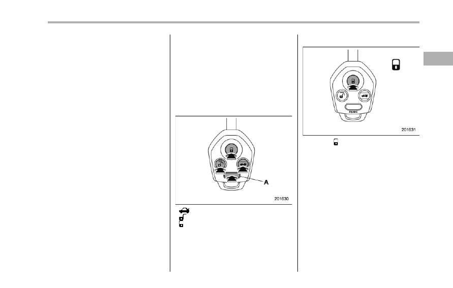
: Rear gate unlock button
: Unlock/disarm button
: Lock/arm button
A: Panic button
& Locking the doors
Press the “ ” button to lock all doors and
rear gate. An electronic chirp will sound
once and the turn signal lights will flash
once.
If any of the doors or the rear gate is not
fully closed, an electronic chirp will sound
five times and the turn signal lights will
flash five times to alert you that any of the
doors or the rear gate is not properly
closed. When you close the door, it will
automatically lock and then an electronic
chirp will sound once and the turn signal
lights will flash once.
Keys and doors
2-9
– CONTINUED –
2-10
Keys and doors
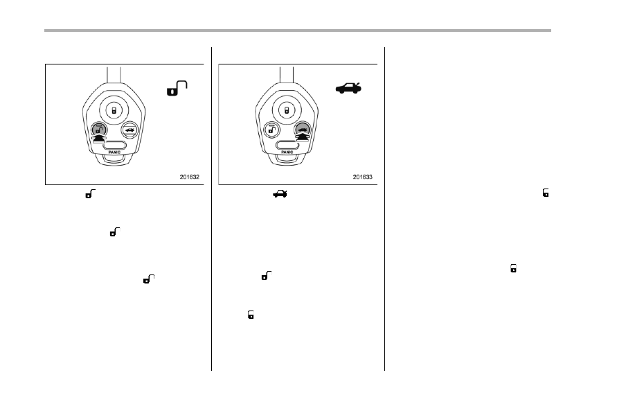
& Unlocking the doors
Press the “ ” button to unlock the driver’s
door. An electronic chirp will sound twice
and the turn signal lights will flash twice.
To unlock all doors and the rear gate,
briefly press the “ ” button a second time
within 5 seconds.
NOTE
If the interval between the first and
second presses of the “ ” button (for
unlocking of all of the doors and the
rear gate) is extremely short, the sys-
tem may not respond.
& Unlocking the rear gate
Pressing the “
” button opens the rear
gate.
An electronic chirp will sound twice and
the turn signal lights will flash twice.
& Illuminated entry
Interior lights such as the map light, dome
light and cargo area light will illuminate
when the “ ” button is pressed. These
lights remain illuminated for approximately
30 seconds if any of the doors or the rear
gate is not opened.
If the “ ” button is pressed before 30
seconds have elapsed, these lights will
turn off.
To activate this function, set the following
interior light switches to the indicated
positions:
Map light: OFF position
Dome light: DOOR position
Cargo area light: DOOR position
A SUBARU dealer can change the illumi-
nation period setting of the interior lights in
accordance with your preference. Contact
the nearest SUBARU dealer for details.
& Vehicle finder function
Use this function to find your vehicle
parked among many vehicles in a large
parking lot. Provided you are within 30 feet
(10 meters) of the vehicle, pressing the “ ”
button three times in a 5-second period
will cause your vehicle’s horn to sound
once and its turn signal lights to flash three
times.
NOTE
If the interval between presses is too
short when you press the “ ” button
three times, the system may not re-
spond to the signals from the remote
transmitter.
& Sounding a panic alarm
To activate the alarm, press the “PANIC”
button once.
The horn will sound and the turn signal
lights will flash.
To deactivate the panic alarm, press any
button on the remote transmitter. Unless a
button on the remote transmitter is
pressed, the alarm will be deactivated
after approximately 30 seconds.
& Selecting audible signal op-
eration
Using an electronic chirp, the system will
give you an audible signal when the doors
lock and unlock. If desired, you may turn
the audible signal off.
Do the following to deactivate the audible
signal. You can also use the same steps
to restore the function.
1. Sit in the driver’s seat and shut all
doors and the rear gate.
2. Hold down the UNLOCK side of the
power door locking switch.
3. While holding down the “UNLOCK”
side of the power door locking switch, pull
the key out and re-insert it into the ignition
switch at least 6 times within 10 seconds
after Step 2.
4. Open and close the driver’s door once
within 10 seconds after step 3.
5. The turn signal lights flash 3 times to
indicate completion of the setting.
You may have the above settings done by
your SUBARU dealer.
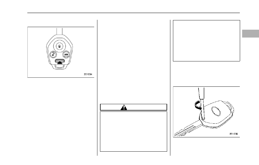
& Replacing the battery
CAUTION
. Do not let dust, oil or water get on
or in the transmitter when repla-
cing the battery.
. Be careful not to damage the
printed circuit board in the trans-
mitter when replacing the battery.
. Be careful not to allow children to
touch the battery and any re-
moved parts; children could
swallow them.
. There is a danger of explosion if
an incorrect replacement battery
is used. Replace only with the
same or equivalent type of bat-
tery.
. Batteries should not be exposed
to excessive heat such as sun-
shine, fire or the like.
When the transmitter battery begins to get
weak, transmitter range will begin to
decrease. Replace the battery as soon
as possible.
To replace the battery:
1. Remove the screw on the key head.
Keys and doors
2-11
– CONTINUED –
2-12
Keys and doors
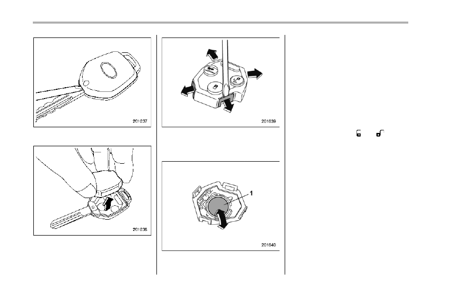
2. Open the key head using a flat-head
screwdriver.
3. Remove the transmitter case from the
key head.
4. Open the transmitter case by releasing
the hooks.
5. Remove the old battery from the
holder.
1)
Negative (−) side facing up
6. Replace with a new battery (Type
CR1620 or equivalent) making sure to
install the new battery with the negative
(−) side facing up.
7. Put together the transmitter case by
fitting the hooks on both sides of the case.
8. Put the transmitter case in the key
head and then put together the key head.
9. Reinstall the screw on the key head.
After the battery is replaced, the trans-
mitter must be synchronized with the
remote keyless entry system’s control
unit. Press either the “ ” or “ ” button
six times to synchronize the unit.
& Replacing lost transmitters
If you lose a transmitter or want to
purchase additional transmitters (up to
four can be programmed), you should re-
program all of your transmitters for secur-
ity reasons. It is recommended that you
have your dealer program all of your
transmitters into your system.
! Programming the transmitters
The remote keyless entry system is
equipped with a special code learning
feature that allows you to program new
transmitter codes into the system or to
delete old ones. The system can learn up
to four unique transmitter codes. The four
transmitter codes may be the same or
different.
Programming transmitter codes into
system:
Key tag
Transmitter circuit board
To register a new transmitter with the
remote keyless entry system, it is neces-
sary to program the transmitter’s code
(identification number) into the system. A
tag showing the code is affixed to the key
unit, and another is affixed to the circuit
board inside the transmitter. If there is no
tag, open the transmitter case and make a
note of the eight-digit number. Program
the number into the system in accordance
with the following procedure.
1. Firmly close the doors and the rear
gate.
2. Open the driver’s door, sit on the
driver’s seat, and close the door.
3. Perform the following steps within 45
seconds.
(1) Open and close the driver’s door
once.
1)
LOCK
2)
ON
(2) Insert the key into the ignition
switch, then turn it from the “LOCK”
position to the “ON” position 10 times
within 15 seconds.
NOTE
. When you complete step (2), an
electronic tone will sound once, a
buzzer will continue to sound and the
interior light will continue to flash until
the transmitter codes are completely
registered.
. If you do not perform steps (1) and
(2) within 45 seconds, an error will
occur. Neither an electronic tone nor
the buzzer will sound, and the interior
lamp will not flash. In this event, per-
Keys and doors
2-13
– CONTINUED –
2-14
Keys and doors
form the whole procedure again begin-
ning with part 1.
4. Open and close the door once within
15 seconds.
NOTE
. When part 4 of the procedure is
completed, an electronic tone will
sound for 30 seconds.
. If you do not perform the operations
in part 4 within 15 seconds, an error
will occur and the electronic tone will
not sound. In this event, perform the
registration steps again beginning with
part 3 of the procedure.
5. Before the electronic tone stops
sounding, push the “ ” side of the power
door locking switch the same number of
times as the leftmost digit of the transmit-
ter code. For example, push the locking
switch eight times if the leftmost digit of
the code is 8.
NOTE
. The electronic tone will stop sound-
ing when you start entering the num-
ber.
. If you do not start entering the
number using the lock knob before
the electronic tone stops sounding, an
error will occur. In this event, perform
the registration steps again beginning
with part 3 of the procedure.
. If the interval between one push of
the knob and the next exceeds 5
seconds, an error will occur. In this
event, perform the procedure again
beginning with part 4. If an error occurs
six times, perform the procedure again
starting with part 3.
6. When you have finished entering the
number, push the “ ” side of the locking
switch within 5 seconds.
NOTE
. An electronic tone will sound.
. If you push the “ ” side of the
locking switch when more than 5
seconds have passed, an error will
occur. In this event, perform the proce-
dure again beginning with part 4. If an
error occurs six times, perform the
procedure again starting with part 3.
7. Perform parts 5 and 6 of the procedure
for each of the remaining digits of the
transmitter code beginning with the sec-
ond digit (counting from the left) and
finishing with the eighth digit.
Нет комментариевНе стесняйтесь поделиться с нами вашим ценным мнением.
Текст